Introduction
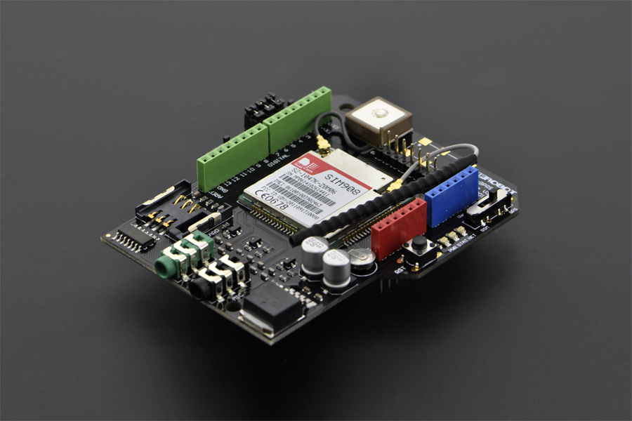
This is a GPS/GPRS/GSM arduino shield from DFRobot. This shield with a Quad-band GSM/GPRS engine works on frequencies EGSM 900MHz/DCS 1800MHz and GSM850 MHz/PCS 1900MHz. It also supports GPS technology for satellite navigation. It's possible for your robot and control system to send messages and use the GSM network.
It is controlled via AT commands(GSM07.07 ,07.05 and SIMCOM enhanced AT Commands). And the design of this shield allows you to drive the GSM & GPS function directly with the computer and the Arduino Board. It includes a high-gain SMD antenna for GPS & GSM.
This GPS/GPRS/GSM shield uses an embedded SIM908 chip from SIMCom.Featuring an industry-standard interface and GPS function, the combination of both technologies allows goods, vehicles and people to be tracked seamlessly at any location and anytime with signal coverage.
Specification
- Power supply: 6-12V@2A
- Low power consumption (100mA@7V - GSM mode)
- Quad-Band 850/900/1800/1900MHz
- GPRS multi-slot class 10
- Support GPS technology for satellite navigation
- Embeded high-gain SMD antennas for GPS & GSM
- Directly support 4*4 button pad
- USB/Arduino control switch
- Board Surface:Immersion Gold
- Size: 81x70mm
Pin Out

User Interface
1.Module driver pin Jumpers
Applying the Module Pin Jumpers(J10-J12) will allocate Pin 3,4,5 for driving the module. Removing the jumpers will release the above Pins, and you could connect the driver pins to the other digital pins on your board to avoid the pin conflict.
2.Switches
Switch S1: Comm/ Prog PC communicates with TEL0051 Module/ Arduino Programming
Switch S2: USB/ Arduino TEL0051 Module directly connects with PC through USB port/ Module communicates with Arduino board
Switch UART Select (S3 we call it in this wiki): Connect the module driver pins to Arduino D3,4,5 Enable GPS or GSM function. You can also use them both at the same time, just leaving the switch in the middle and use code to enable GPS/ GSM alternatively.
NOTE: Version difference from V1 to V3
GSM high-gain antenna has been removed
GPS/GSM UART selection has been replaced by a Three-position Switch: UART Select. And "Take off the jumper caps" do the same function as "slid the switch in the middle".

| NOTE: Version difference from V1 to V3 GSM high-gain antenna has been removed GPS/GSM UART selection has been replaced by a Three-position Switch: UART Select. And "Take off the jumper caps" do the same function as "slid the switch in the middle". |
|---|
3.LED
PWR: To indicate if the module get power.
STAT: If the module is enabled, it will turn on, this means that the module is running correctly.
Network LED: It will turn on when network is ready.
| State | SIM908 behavior |
|---|---|
| Off | SIM908 is not running |
| 64ms On/ 800ms Off | SIM908 not registered the network |
| 64ms On/ 3,000ms Off | SIM908 registered to the network |
| 64ms On/ 300ms Off | PPS GPRS communication is established |
Tutorial
Requirements
- Hardware
- Arduino Uno
- GPS/GPRS/GSM Module V3.0
- SIM Card
- Earphone & Microphone
- External power supply, 7-12V@2A
- Software
- Coolterm or
DF Serial Debugger by Lisper, we use the first one in the wiki. - Arduino IDE, any version is fine, Click to Download Arduino IDE
- Coolterm or
Sample Code
- Click here to download.
Basic things you need to know
1. How to upload a sketch to Arduino card once got the module stacked on?
The module will occupy the serial port if you switch S1 to Comm, so once you release the serial port by switching S1 to Prog, you could upload a sketch in normal.
2. How to enter AT mode, sending AT command?
1.Insert an available SIM card onto the module (not necessary for GPS test), stack the module on Uno, then use a USB cable to connect Uno to PC. PWR LED will turn on as red.
If you want to test GSM function like send a message, call somebody... you have to supply UNO with an external power.
2.Open Arduino IDE, choose "board" & "port" in Menu bar.
3.Upload code to disable/ enable different function of this module according to your test, seen in following specific section.
4.Check the switch position, S1: Comm; S2: USB; S3: for gps AT test_GSM OR for gsm AT test_middle.
5.Open Arduino serial monitor or use other serial helper (Coolterm is used here, for Arduino serial monitor can not send command in HEX).
6.Choose "9600" & "Both NL&CR" (or "Carriage Return") as the command format.
7.If the STAT & NET LED turned off, please hit the button RST to reboot the module.
8.After the STAT LED is on, and some RDY(ready) notices printed on your screen, then you could send AT commands to use the module.
Serial Command Format setting
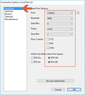
CoolTerm Serial command setting:"9600"
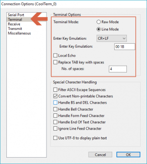
CoolTerm Serial command setting "CR LF" or "CR"

Arduino IDE Serial command setting: "9600" & "Both NL&CR" (or "Carriage Return")
3. About GSM mode & GPS mode Selection
Except using UART selection jumper caps(old version)/ the switch(latest version), alternatively, you could also switch GSM and GPS function with the IO pins, but please remove the jumper caps connected for hardware UART selection(old version)/ set the switch in middle(latest version) in this case.
| NOTE: You could control GPS through the GSM AT commands, without requiring to enable both independently. This way you can let the GPS enabled while using GSM network. Thus not triggering a GPS reset. |
|---|
Drive the module via USB port (AT command)
How to drive the GPS Mode via USB port
| NOTE: You have to take the module outdoor to get valid GPS data. If you are only to test its AT command, you can stay inside. |
|---|
Steps:
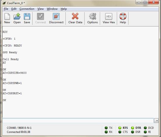
Code for GPS feature, AT mode
- Stack this GPS/GSM shield onto Arduino UNO (Leonardo is special, you could go to FAQ, Q8 to know how), then connect UNO to computer with a USB cable.
- NOTE: The SIM card & External power source can be omitted here, we don't need that so far. But if you have inserted a SIM card onto the module, you do NEED an external power then, a mere USB power is NOT capable to run it!
- Turn the S1 to Prog
- Upload the sample code "Code for GPS feature, AT mode" in right
- Turn the three switches to: S1: Comm, S2: USB, S3(UART): GSM
- Connect the CoolTerm serial port
- The Serial monitor command format should be set as 9600, CR LF in Option.
- If you found the STAT & NET led turned off, please press RST button (or disconnect and re-connect the serial port) to reboot the module.
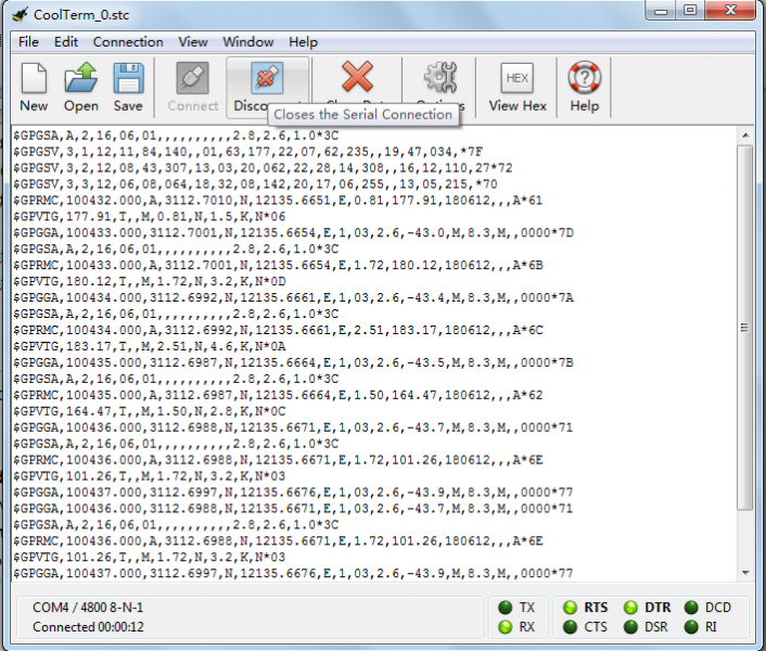
- Send AT commands below, you will receive corresponding OK from the module as showing in the picture
- Send: AT
- Send: AT CGPSIPR=9600 (set the baud rate)
- Send: AT CGPSPWR=1 (turn on GPS power supply)
- Send: AT CGPSRST=1 (reset GPS in autonomy mode)
- Turn the switch S3(Uart) to the GPS, you could receive the GPS data.
- If you want turn GPS off.
- Turn the Uart switch to GSM side
- Send AT CGPSPWR=0(turn off GPS power supply, in code)
- Send AT CPOWD=1 ( turn off GSM/GPS/GPRS module, in code)
- If you want to restart the module, press RST button please.
| NOTE: What is the meaning of GPS data received? Please refer to Location Mapping (GPRMC), you could also go to FAQ>Q2 for more info. |
|---|
How to Send a message
| NOTE: Before you test GSM function using AT command (including Make a call or other function related to GSM). You have to upload the code below to enable GSM. |
|---|
Steps:
Code for GSM feature, AT mode
- Repeat the steps in NO.2 How to enter AT mode, sending AT command? to enter AT mode.
- You should upload the code "Code for GSM feature, AT mode" this time in right
- After you entered AT mode, you can:
- Send: AT
- Send: AT CMGF=1 (set the message to text format)
- Send: AT CMGS="XXXXX" (xxxx is the number of receiver)
- After you see ‘>’ then type the message you want to send
- Press 'ctrl Z' to send. (If you want to cancel, you can press ESC)
- NOTE: This step depends on the Serial software you use and its configuration. Arduino Serial Monitor can not accomplish this. Please go to the section below, "Ways to send Ctrl Z in Coolterm", for more details.
- Then you will see "OK". After several seconds, the receiver should get a message from this shield.

Ways to send Ctrl Z in Coolterm
Method 1. After typing the message text, press enter key, it will show:

Then, in the input area, pressing Ctrl Z will send out the single CTRL character successfully as below:
Note: This key shortcut depends on your version and configuration.

Method 2. Ctrl characters can also be sent out in their hexadecimal, Ctrl Z = '1A', this avoids problems with Coolterm version and configurations.
This method can be used with other Serial softwares, e.g. [DF Serial Debugger by Lisper](https://github.com/leffhub/DFRobotSIM808_Leonardo_mainboard/raw/master/Software/DF Serial Debugger.exe)), clike here to know more detals about how.

How to Make a phone call
Steps:
- Send: AT
- Send: ATDXXXXXXX;(xxxxxxx is the number of receiver, please do not forget the semicolon ";")
- Then you will see "OK". And after several seconds, the receiver should get a phone call from this shield.
- If you want to cancel/ hang up the call, send: ATH
- ATA : Answer the phone

How to drive the module via Arduino board
How to Send a message
| NOTE: Before you upload the sketch to the Arduino board, please turn the S2 switch to the Arduino side(left side), or you will not be able to register to the network. |
|---|
You can see:

After several seconds, the receiver will get a message from this shield
When you send the SMS "LH" to the module, it WILL turn led on; when you send the SMS "LL", it will be turned off.
How to Make a phone call
You can see: 
After several seconds,the receiver will get a phone call from this shield
How to drive the GPS Mode via Arduino board
- S1 - Comm
- S2 - Arduino
- S3 - UART ( Middle)
Sample code could be found here.
Project Sharing
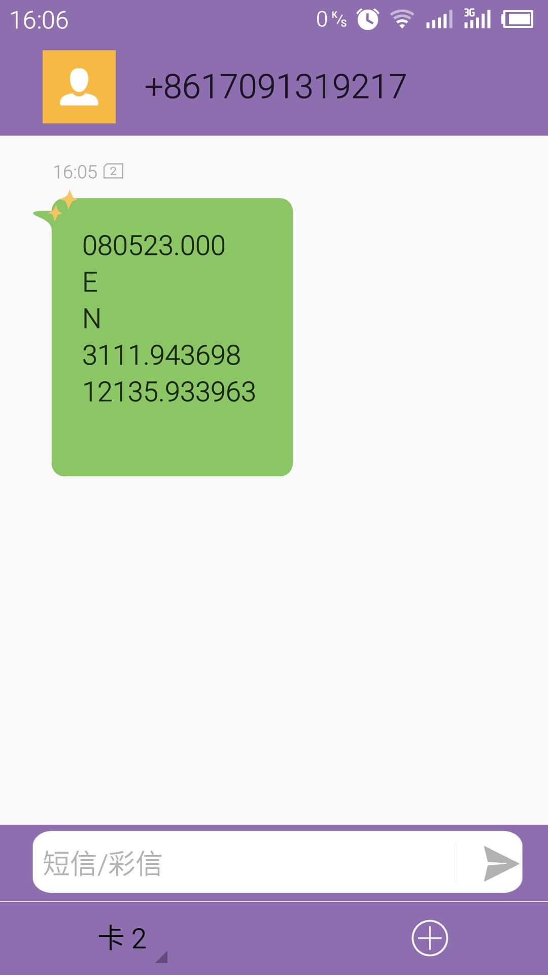
This code will send GPS information to your phone via SMS. As the picture at right hand.
- Please download the library.
- Fill your phone number into the code.
- Upload the sketch to your Arduino board, after about 5-10 minutes according to your GPS signal intensity.
FAQ
| - | Some general Arduino Problems/FAQ/Tips |
|---|---|
| Q | If the module is not working properly, plz check |
| A | ①SIM card should be in service ② Switches should in right position ③ The external power supply should be 7-12V@2A ④ Check signal range, best to be on an area with full coverage. ⑤ Signal for GPS has best performance on a clear direct line of sight with sky, even better with less buildings around. ⑥ GPS needs time to connect to at least 4 satellites to output data. ⑦ AT command tester by one of our contributors. |
| Q | What's the minutes and seconds of coordinate data? |
| A | The raw gps information from the serial is in the form: DDmm.mmmmm. e.g.If the raw information is: 5320.12345, then it is: 53 degress and 20.12345 minutes. In order to convert it to decimal coordinates you divide the minutes by 60. i.e. 20.12345 / 60 = .33539 Finally, the decimal result: 53.33539 |
| Q | Can this module support FTP, if yes, how? |
| A | Yes, it supports, please check here on Forum, shared by dfrobot. |
| Q | I have tried restarting the shield multiple times, each time the shield initiate normally with Stat and Net LED turned on. The moment I connect to the shield via serial, both green light would turn off. I had tried diagnosing the problem with Module Tester(Serial monitor). On the rare occasion a connection was establish, it would display a response like normal power off. What's the problem with it? |
| A | Once the module detect the serial signal_Reset, it will reset, then the module would power down, namely the State and NET LED would turn off. And the the Reset signal can be triggered by any one of these operation ① hit the botton_RST(reset) on the shield/ Arduino card ② when you pull the switch_S1 from Prog to Comm (or contrary) ③ when you open Arduino Serial Monitor or connect the serial port by other Serial Testers.To reboot the module (light up the State&Net LED), you can hit the button_Reset or you can re-open the Serial Monitor. |
| Q | I used Leonardo with the sample codes in this section "How to drive the module via Arduino board", also I changed the Serial.xxx() to Serial1.xxx() to adapt to Leonardo, and it worked. But in this section "Drive the module via USB port (AT command)", what should I do?  |
| A | Hi, you are right that to modify the Serial into Serial1 for Leonardo using the sample sketches. But for to AT mode, it is very similar to this board, SIM808 with Leonardo mainboard SKU:DFR0355, i.e. you have to use the code below (For GPS debug) for AT command debugging, also the switches should be set as: S1: Comm; S2: Arduino; S3 should set as the same as above tutorial. One more note is the external power should be added as Leonardo costs more power even in GPS feature test. |
For any questions/advice/cool ideas to share, please visit DFRobot Forum.