Introduction
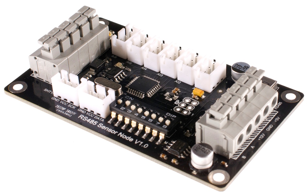
This RS-485 Sensor Node module can be used in various applications such as intelligent agriculture, environment monitoring,home automation...etc. It is a Internet of things device. This RS-485 Sensor node provides 6 channel analog input and 1 SHT1x Humidity & Temperature digital input. The RS485 protocol supports up to 254 nodes at 1200m distance between each node. This allows a wide range cover for monitoring the environment. A screw free design allows easy connection of cables without scarfice reliable & stable.
RS-485 standard is used effectively over long distances and in electrically noisy environments. Multiple receivers may be connected to such a network in a linear, multi-drop configuration. These characteristics make such networks useful in industrial environments and similar applications.RS-485 enables the configuration of inexpensive local networks and multidrop communications links. It offers data transmission speeds of 35 Mbit/s up to 10 m and 100 kbit/s at 1200 m.
RS-485 bus is the most popular communication method in industry. Compared with RS-232 bus, it is able to transfer information in further distance with lower cost. Establishing an “Internet of Things” by integrating RS-485 with Ethernet, which is the widely available in the world, in the hope that this method will coordinate all devices with low cost and high efficiency.
Application
- Intelligent agriculture
- Public safety
- Environment monitoring
- Individual health
- Home automation
Specification
- MCU:Atmega8
- Input Voltage:12V
- Baud rate:9600
- Slave address: 0x01 - 0x7F
- RS-485 long distance,reliable & stable conmunication
- Multiple connection(up to 127 modules)
- Press to connect cables, quick and easy
- 1 SHT1x Humidity and Temperature Sensor interface
- 6 channel analog sensor interface
- 8 small switches for setting slave address directly
- Humidity:0-100%RH(±4.5%RH)
- Temperature:-40-128.8℃(±0.5℃)
- Size:82x50mm
Pin Out

More details

Auto or manual operation: This bit is for setting the addresses of slave devices by software or hardware.
- A: set slave address via software, when it is at the A side, the Bits for setting slave address will be invalid.
- M: set slave address via hardware, when it is at the M side means you can set the slave address via the 7 small switches.Success to set after 30 seconds.
Bits for setting address of slave: 0x01~0x7F,just be effective to M side
Product Directive
- Check all the current real-time data directive--0x21
Command:
| Word Head | Device Address | Frame Length | Command Word | Checksum |
| 0x55 | 0xAA | 0x11 | 0x00 | 0x21 |
This command will check all data of current device.There are 10 register data totally.A register data is 16 digit,consisting of 8 high digit and 8 low digit.
Return the following:
| Content Order | Register Illustration | Register Data | Register Range |
| 1 | manually/automatically set address status | 0x00 0x01 | 1 for automatic; 0 for manual |
| 2 | Humidity Measurement | 0x00 0x02 | 0.0 to 100.0%(RH) |
| 3 | Temperature Measurement | 0x00 0x03 | -40.0 to 128.0(℃) |
| 4 | SHT1X error status | 0x00 0x04 | 1 for error; 0 for normal |
| 5 | Analog Measurement 1 | 0x00 0x05 | 0 to 1023 |
| 6 | Analog Measurement 2 | 0x00 0x06 | 0 to 1023 |
| 7 | Analog Measurement 3 | 0x00 0x07 | 0 to 1023 |
| 8 | Analog Measurement 4 | 0x00 0x08 | 0 to 1023 |
| 9 | Analog Measurement 5 | 0x00 0x09 | 0 to 1023 |
| 10 | Analog Measurement 6 | 0x00 0x10 | 0 to 1023 |
'''Instruction Description: content value consists of 2 byte; 0.0 to 100.0 degree stand for 0 to 1000; -40.0 to 128.0 degree stand for -400 to 1280 '''
Return Value:
| Word Head | Device Address | Frame Length | Command Word | Content | Checksum |
| 0x55 | 0xAA | 0x11 | 0x14 | 0x21 | H |
Sample:
Send instruction:
| Word Head | Device Address | Frame Length | Command Word | Checksum |
| 0x55 | 0xAA | 0x11 | 0x00 | 0x21 |
Return instruction:
| Word Head | Device Address | Frame Length | Command Word | Content1 | Content2 | Content3 |
| 0x55 | 0xAA | 0x11 | 0x14 | 0x21 | 0x00 0x00 | 0x00 0x00 |
| Content4 | Content5 | Content6 | Content7 | Content8 | Content9 | Content10 |
| 0x00 0x01 | 0x00 0x66 | 0x00 0x99 | 0x00 0x66 | 0x00 0x99 | 0x00 0x66 | 0x00 0x99 |
- Set address for the model --0x55
Command:
| Word Head | Device Address | Frame Length | Command Word | Content | Checksum |
| 0x55 | 0xAA | 0xAB | 0x01 | 0x55 | 0x22 |
Return Value:
| Word Head | Device Address | Frame Length | Command Word | Content | Checksum |
| 0x55 | 0xAA | 0xAB | 0x01 | 0x55 | 0x22 |
Instruction Description: 0xAB is broadcast address,that is, it is shared address of all models. Send 0x55 to address 0xAB in order to set model address in the uncertain model status
According to new device address,model will return 0x55 after address set successfully; In manual status,sending 0x55 can't set current device address,if the product can set device address manually and automatically.Then, the return value is 0xFE that illustrates product in manual setting address status.
Return Value:
| Word Head | Device Address | Frame Length | Command Word | Content | Checksum |
| 0x55 | 0xAA | 0xAB | 0x01 | 0x55 | 0xFF |
Sample:
Send instruction:
| Word Head | Device Address | Frame Length | Command Word | Content | Checksum |
| 0x55 | 0xAA | 0xAB | 0x01 | 0x55 | 0x11 |
this sample is used for setting device address as 0x11.
In the status of setting address manually
Send instruction:
| Word Head | Device Address | Frame Length | Command Word | Content | Checksum |
| 0x55 | 0xAA | 0xAB | 0x01 | 0x55 | 0x11 |
Return instruction:
| Word Head | Device Address | Frame Length | Command Word | Content | Checksum |
| 0x55 | 0xAA | 0xAB | 0x01 | 0x55 | 0xFF |
Connecting Diagram

Sample Code
FAQ
For any questions, advice or cool ideas to share, please visit the DFRobot Forum.