Introduction
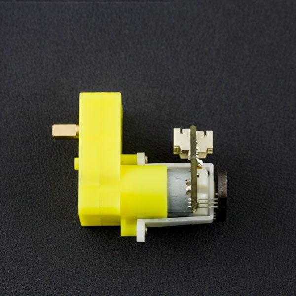
This is the DFRobot Micro DC geared motor with encoder. It is a motor with a 120:1 gearbox and an integrated quadrature encoder that provides a resolution of 8 pulse single per round giving a maximum output of 960 within one round. With an Arduino controller and motor driver, applications for this might include a closed-loop PID control or PWM motor speed control. This motor is an ideal option for mobile robot projects. The copper output shaft, embedded thread and reinforced connector greatly extends the motor's service life.
Specification
- Gear ratio: 120:1
- No-load speed @ 6V: 160 rpm
- No-load speed @ 3V: 60 rpm
- No-load current @ 6V: 0.17A
- No-load current @ 3V: 0.14A
- Max Stall current: 2.8A
- Max Stall torque: 0.8kgf.cm
- Rated torque: 0.2kgf.cm
- Encoder operating voltage: 4.5~7.5V
- Motor operating voltage: 3~7.5V (Rated voltage 6V)
- Operating ambient temperature: -10 ~ +60℃
Board Overview

| Grade | Name | Functional Description |
|---|---|---|
| + | Motor power supply pin + | 3-7.5V,Rated voltage6V |
| - | Motor power supply pin - | |
| VCC | Encoder supply + | 4.5-7.5V |
| GND | Encoder supply GND | |
| B | Encoder B phase output | Changes square wave with the output frequency of Motor speed(interrupt port) |
| A | Encoder A phase output | Changes square wave with the output frequency of Motor speed |
Tutorial
Ready to work
- hardware
- DFRduino UNO x1
- DC power supply x1
- L298 x1
- software
- Arduino IDE Download Arduino IDE
Connection Diagram

This tutorial is intended to use the encoder, Select D2 pin and D3 pin, Wherein D2 as an interrupt port, D3 as an input pin. In practice, two pins need to ensure that one of pins must be an interrupt pin, and the other definable (see the interrupt port with different board).
Interrupt Port with Different Board
Notcie: attachInterrupt() 
If using an Arduino UNO and you want to use interrupt port 0 (Int.0), you need to connect digital pin D2 on the board. The following code is only used in UNO and Mega2560. If you want to use Arduino Leonardo, you should change digital pin D3 instead of digital pin D2.
See the link for details https://www.arduino.cc/reference/en/language/functions/external-interrupts/attachinterrupt/
Sample Code 1
Code 1 Expected Output:
Explanation: Here you can see serial data. When the motor turns forward, the digital output value is > 0. When the motor reverses direction, digital output < 0. The faster the motor's speed, the greater the value of the number.

Sample Code 1
PID control: PID algorithm to control the motor speed by L298P DC motor driver board
- Motor power port is connected to the L298 drive motor M1 port
- Download and install Arduino PID
Code 2 Expected Behaviour: The code PID value has been set as 80, so the motor will stabilize at about 80 rpm. If outside forces such as changes in motor drive voltage, the motor's resistance, etc affect the speed, the program will adjust the PWM value to stabilize the rotational speed at 80.
FAQ
| Q&A | Some general Arduino Problems/FAQ/Tips |
|---|---|
| A | For any questions, advice or cool ideas to share, please visit the DFRobot Forum. |
More Documents
- [Motor dimension drawing](https://github.com/Arduinolibrary/DFRobot_Micro_DC_Geared_Motor_with_Encoder/raw/master/FIT0458 Micro DC Motor with Encoder-SJ02.pdf)