introduction
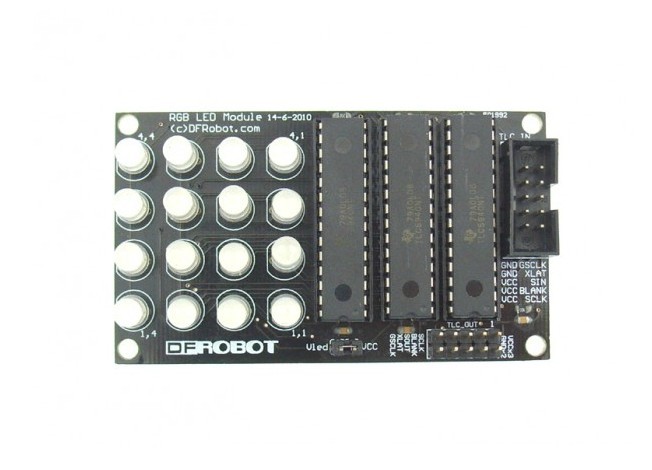
This Arduino-compatible module uses three TI TLC5940 PWM LED chips to drive a 4x4 array of RGB LEDs. Each color is controlled by a different chip so you can adjust the reference resistors for the appropriate current. The TLC5940 chips are not directly connected to any Arduino pins, but a header is provided for you to make a manual connection depending on the needs of your sketch.
The module can be serially linked to make a wall or circle. (Up to 16 modules)
This module comes with assemblied and can be directly plugged into our Interface shield. The link is conducted by IDC2x5 cables. It can also be directly connected to Arduino via the F/M cables.
Specifications
- 16 Channels
- 12 bit (4096 Steps) Grayscale PWM Control
- Dot Correction
- 6 bit (64 Steps)
- Storable in Integrated EEPROM
- Drive Capability (Constant-Current Sink)
- 0 mA to 60 mA (VCC < 3.6 V)
- 0 mA to 120 mA (VCC > 3.6 V)
- LED Power Supply Voltage up to 17 V
- VCC = 3 V to 5.5 V
- Serial Data Interface
- Controlled In-Rush Current
- 30MHz Data Transfer Rate
- CMOS Level I/O
- Error Information
- LOD: LED Open Detection The LED open detection
- TEF: Thermal Error Flag
Connection diagram

User guides
Hardware preparation
If you have interface shield, just plug in IDC2x5 cables. Please see connection diagram.
Otherwise see Basic Pin setup:
| ARDUINO | ARDUINO | u | u | u | u | |
|---|---|---|---|---|---|---|
| 13 | -> SCLK (pin 25) | OUT1 | 1 | 28 | OUT channel 0 | |
| 12 | OUT2 | 2 | 27 | -> GND (VPRG) | ||
| 11 | -> SIN (pin 26) | OUT3 | 3 | 26 | -> SIN (pin 11) | |
| 10 | -> BLANK (pin 23) | OUT4 | 4 | 25 | -> SCLK (pin 13) | |
| 9 | -> XLAT (pin 24) | . | 5 | 24 | -> XLAT (pin 9) | |
| 8 | . | 6 | 23 | -> BLANK (pin 10) | ||
| 7 | . | 7 | 22 | -> GND | ||
| 6 | . | 8 | 21 | -> VCC (+5V) | ||
| 5 | . | 9 | 20 | -> 2K Resistor -> GND | ||
| 4 | . | 10 | 19 | -> +5V (DCPRG) | ||
| 3 | -> GSCLK (pin 18) | . | 11 | 18 | -> GSCLK (pin 3) | |
| 2 | . | 12 | 17 | -> SOUT | ||
| 1 | . | 13 | 16 | -> XERR | ||
| 0 | OUT14 | 14 | 15 | OUT channel 15 |
If you are daisy-chaining more than one TLC, connect the SOUT of the first TLC to the SIN of the next.All the other pins should just be connected together:
BLANK on Arduino -> BLANK of TLC1 -> BLANK of TLC2 -> ...
XLAT on Arduino -> XLAT of TLC1 -> XLAT of TLC2 -> ...
- The one exception is that each TLC needs it's own resistor between pin 20 and GND.This library uses the PWM output ability of digital pins 3, 9, 10, and 11. Do not use analogWrite(...) on these pins.
Software preparation
- Download the Arduino library. It includes several head files. The most fundamental ones are "Tlc5940.h" and "tlc_config.h". The first one contains the most basic functions to control the LED arrays and the second one is variable declaration.
Sample code
- Notation:
- Change the value of defined invariable NUM_TLCS ( In the file: "tlc_config.h" incuded in the library folder: "Tlc5940".) from 3 to 6(if you want cascade two LED modules), to 9(if you want cascade three LED modules)...
- The order of channel is determined by the order of TLC microcontroller. channnel 0-15 are 16 red LEDs controlled by the first TLC microcontroller. channel 16-31 are 16 green LEDs, channel 32-47 are 16 blue LEDs. One RGB modules has 3 TLC microcontrollers and if you want to use two RGB LED modules, channel 48-63 are 16 red LEDS of second module, and so on. See function: Tlc.set(channel,brightness). This is the function which turns one specific LED on.
- Let's see sample 1.
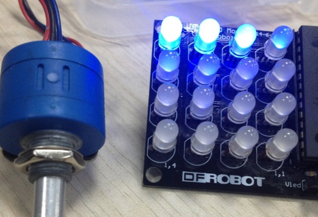
Sample 1 is a demo of controllable LED color tuning and fading. It uses the library "tlc_fades.h". If you have a potentiometer,it will be better. Otherwise, you can connect the analog port 0 to 5V or ground to observe the changes. Substitute the parameter "TLC_FADE_BUFFER_LENGTH" in head file "tlc_fades.h" to 40.
- Let's see sample 2. Sample 2 needs another two headfiles "basicProcess.h" and "message.h". Copy them under the same folder of the Arduino code. It demonstrates simple pattern animation, rolling, etc. Notation, here we need two LED modules.
- Arduino code
- "basicProcess.h"
- "message.h"

