Arduino/Genuino 101 Starter Kit Tutorial - Lesson 5: Electronic Gradienter
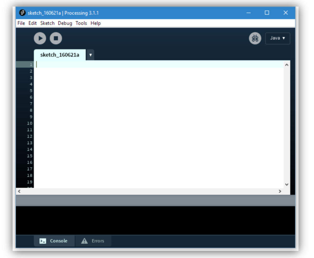
In this chapter, we will be putting together the data collected by the accelerometer and import them into “Processing”, a visual art software sketchbook which Arduino IDE is based on, to plot a 3D model showing the gesture of 101 in real time.
COMPONENTS LIST
No further component is needed in this chapter.
HARDWARE CONNECTIONS
No hardware connection is needed in this chapter.
Build an electronic gradienter
In this section, we will introduce the “Processing”, a wire communication based software that converts real- time data into 3D graphics. Due to the limitation of the space, we will not go deep into but just show you how to import data and plot our object. However, it is strongly recommended to learn more if building visual interactive projects is of your interest.
Download Processing
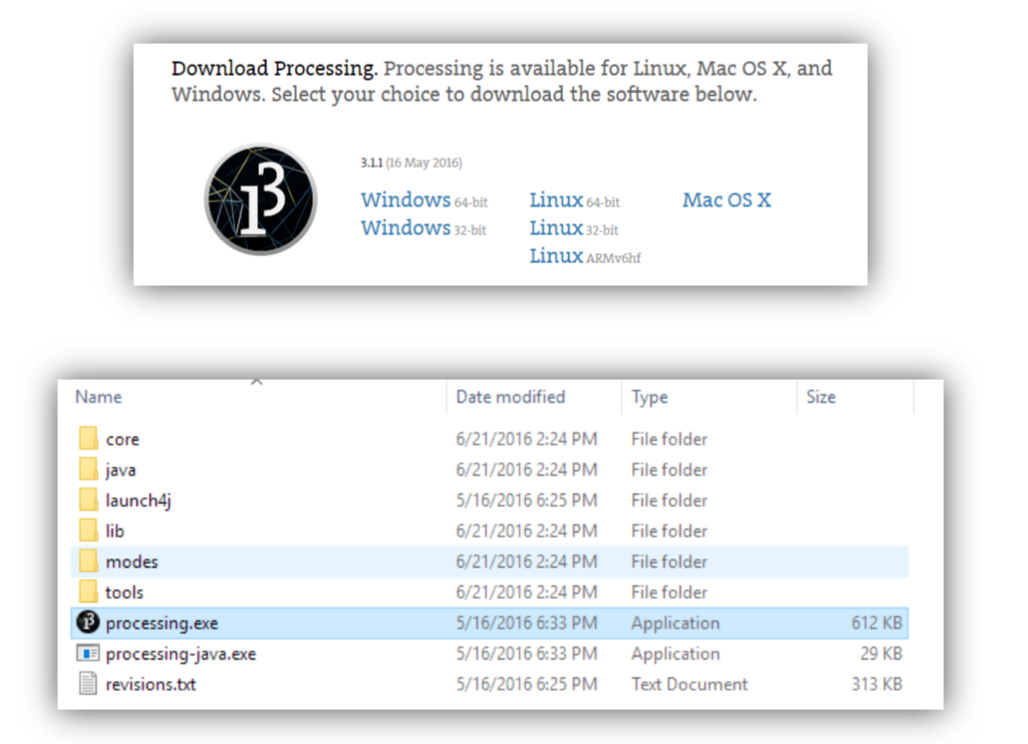
Go to the link below and follow the guide to start download.
https://processing.org/download/
Same as Arduino IDE, Processing is a free open-source software. You may choose the amount of donation of you want then click “Donate & Download” to go to the download page. Download the right version of Processing that is compatible with your operation system. This following part will be based on Windows 64- bit.

To get started, we need first upload code to 101 to set it sending gesture data through serial port. Also, we need code for Processing to set it receiving data and converting into 3D plot.
CODE
Code for Arduino IDE
#include "CurieIMU.h"
#include "math.h"
int16_t ax, ay, az;
int16_t gx, gy, gz;
const int ledPin = 13;
boolean blinkState = false; // state of the LED
void setup() {
Serial.begin(9600); // initialize Serial communication
while (!Serial); // wait for the serial port to open
// initialize device
Serial.println("Initializing IMU device...");
CurieIMU.begin();
// verify connection
Serial.println("Testing device connections...");
if (CurieIMU.testConnection()) {
Serial.println("CurieIMU connection successful");
} else {
Serial.println("CurieIMU connection failed");
}
// use the code below to calibrate accel/gyro offset values
Serial.println("Internal sensor offsets BEFORE calibration...");
Serial.print(CurieIMU.getXAccelOffset());
Serial.print("\t"); // -76
Serial.print(CurieIMU.getYAccelOffset());
Serial.print("\t"); // -235
Serial.print(CurieIMU.getZAccelOffset());
Serial.print("\t"); // 168
Serial.print(CurieIMU.getXGyroOffset());
Serial.print("\t"); // 0
Serial.print(CurieIMU.getYGyroOffset());
Serial.print("\t"); // 0
Serial.println(CurieIMU.getZGyroOffset());
Serial.println("About to calibrate. Make sure your board is stable and upright");
delay(5000);
// The board must be resting in a horizontal position for
// the following calibration procedure to work correctly!
Serial.print("Starting Gyroscope calibration...");
CurieIMU.autoCalibrateGyroOffset();
Serial.println(" Done");
Serial.print("Starting Acceleration calibration...");
CurieIMU.autoCalibrateXAccelOffset(0);
CurieIMU.autoCalibrateYAccelOffset(0);
CurieIMU.autoCalibrateZAccelOffset(1);
Serial.println(" Done");
Serial.println("Internal sensor offsets AFTER calibration...");
Serial.print(CurieIMU.getXAccelOffset());
Serial.print("\t"); // -76
// accelerometer values
// gyrometer values
// activity LED pin
Serial.print(CurieIMU.getYAccelOffset());
Serial.print("\t"); // -2359
Serial.print(CurieIMU.getZAccelOffset());
Serial.print("\t"); // 1688
Serial.print(CurieIMU.getXGyroOffset());
Serial.print("\t"); // 0
Serial.print(CurieIMU.getYGyroOffset());
Serial.print("\t"); // 0
Serial.println(CurieIMU.getZGyroOffset());
Serial.println("Enabling Gyroscope/Acceleration offset compensation");
CurieIMU.setGyroOffsetEnabled(true);
CurieIMU.setAccelOffsetEnabled(true);
// configure Arduino LED for activity indicator
pinMode(ledPin, OUTPUT);
}
void loop() {
// read raw accel/gyro measurements from device
CurieIMU.getMotion6(&ax, &ay, &az, &gx, &gy, &gz);
double unitx, unity;
unitx= double(ax)/sqrt(ax*ax+ay*ay+az*az);
unity= double(ay)/sqrt(ax*ax+ay*ay+az*az);
double pitch, yaw,roll;
yaw = 0;
pitch = -asin(unity/sqrt(1-unitx*unitx)) ;
roll = atan(unitx/sqrt(1-unitx*unitx));
Serial.print(float(yaw));
Serial.print(","); // print comma so values can be parsed
Serial.print(float(pitch));
Serial.print(","); // print comma so values can be parsed
Serial.println(float(roll));
delay (10);
}
Code for Processing
import processing.serial.*;
Serial myPort;
int newLine = 13; // new line character in ASCII
float yaw;
float pitch;
float roll;
String message;
String [] ypr = new String [3];
void setup()
{
size(600, 500, P3D);
/*Set my serial port to same as Arduino, baud rate 9600*/
myPort = new Serial(this, Serial.list()[0], 9600); // if you have only ONE COM port active
//myPort = new Serial(this, "COM5", 9600); // if you know the 101 COM port
textSize(16); // set text size
textMode(SHAPE); // set text mode to shape
}
void draw() {
serialEvent(); // read and parse incoming serial message
background(255); // set background to white
translate(width/2, height/2); // set position to centre
pushMatrix(); // begin object
rotateX(pitch); // RotateX pitch value
rotateY(-yaw); // yaw
rotateZ(-roll); // roll
drawArduino(); // function to draw rough Arduino shape
popMatrix(); // end of object
// Print values to console
print(pitch);
print("\t");
print(roll);
print("\t");
print(-yaw);
println("\t");
}
void serialEvent()
{
message = myPort.readStringUntil(newLine); // read from port until new line (ASCII code 13)
if (message != null) {
ypr = split(message, ","); // split message by commas and store
in String array
yaw = float(ypr[0]); // convert to float yaw
pitch = float(ypr[1]); // convert to float pitch
Instruction
roll = float(ypr[2]); // convert to float roll
}
}
void drawArduino() {
/* function contains shape(s) that are rotated with the IMU */
stroke(0, 90, 90); // set outline colour to darker teal
fill(0, 130, 130); // set fill colour to lighter teal
box(300, 10, 200); // draw Arduino board base shape
stroke(0); // set outline colour to black
fill(80); // set fill colour to dark grey
translate(60, -10, 90); // set position to edge of Arduino box
box(170, 20, 10); // draw pin header as box
translate(-20, 0, -180); // set position to other edge of Arduino box
box(210, 20, 10); // draw other pin header as box
}
Instruction
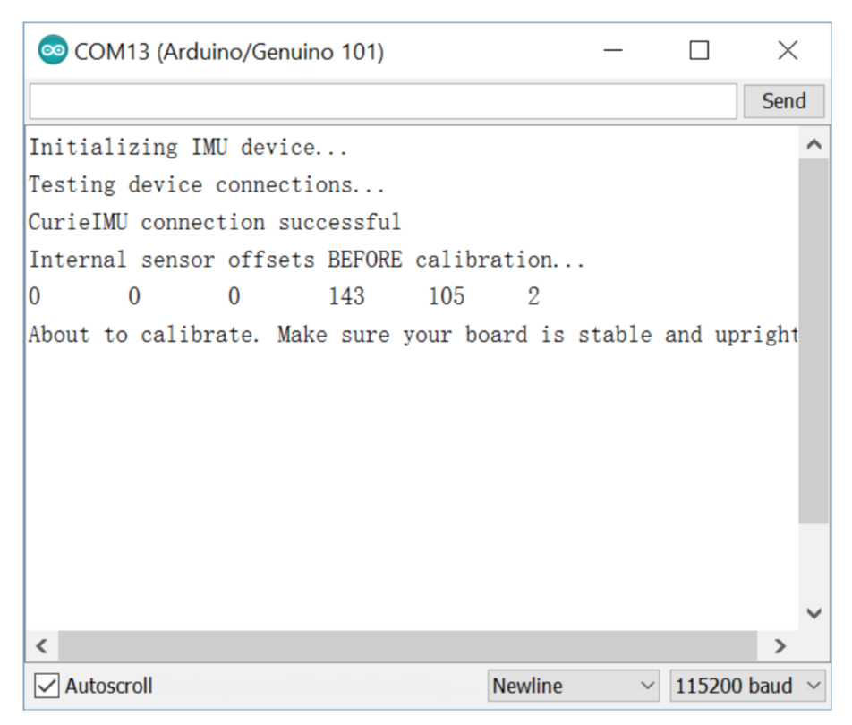
Uploading the code for Arduino IDE into 101. Wait a few seconds till the system boots up. Select the COM port for 101 and open the serial monitor. 101 will run into a calibration procedure once the serial monitor is opened for the first time. Make sure the board is place in still on a flat surface. The entire procedure takes about 10 seconds.
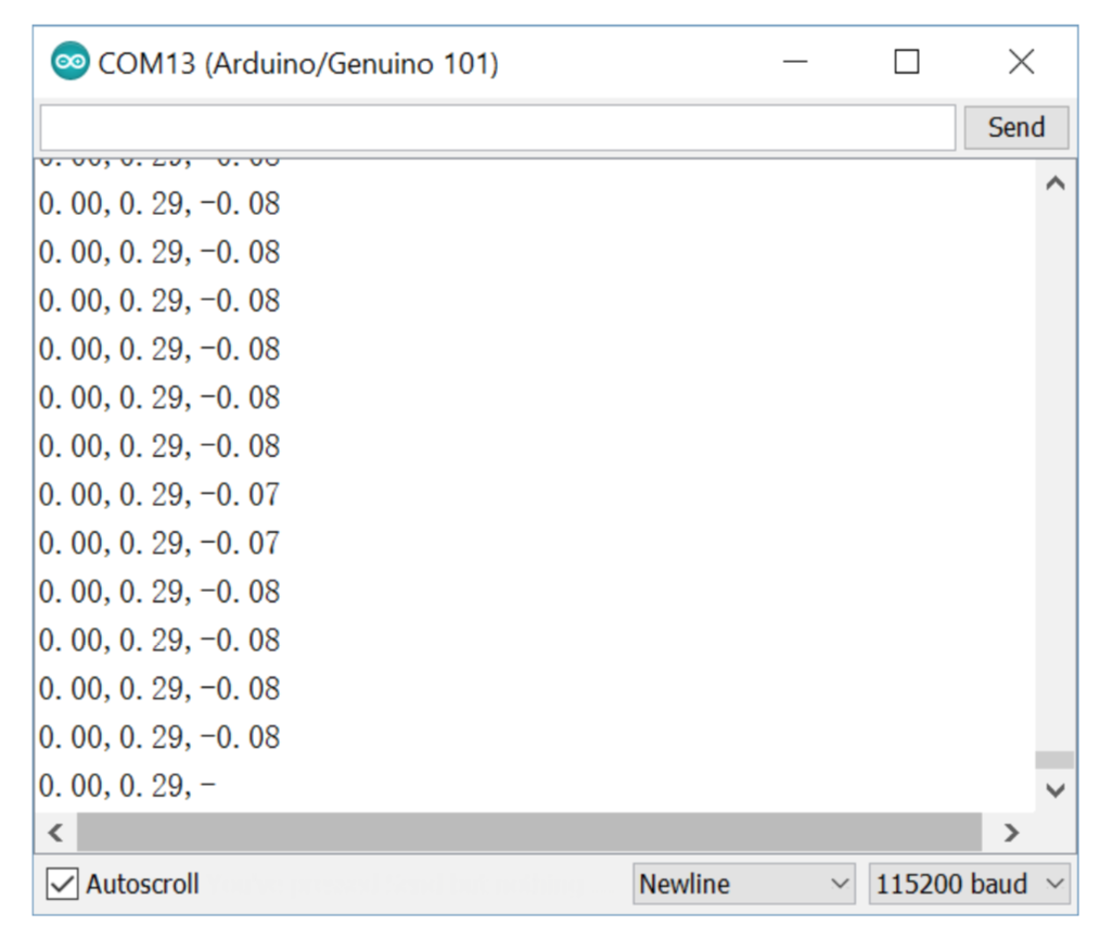
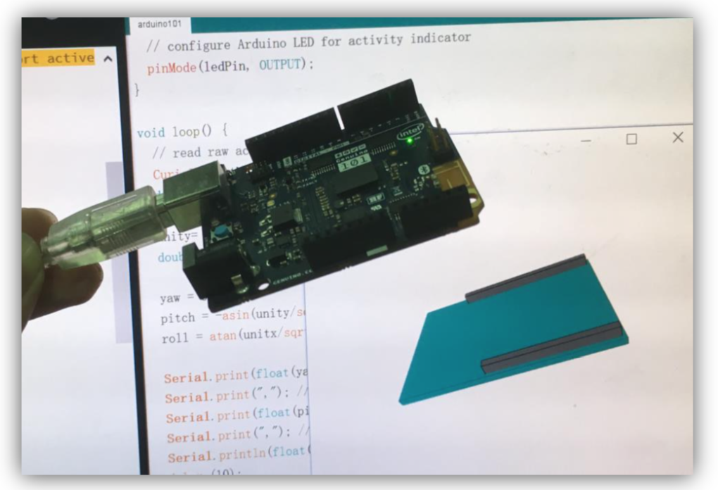
Once the calibration is done, 101 starts sending gesture data in the format of yaw, pitch, roll, each divided by comma. Since we will only use the measurements from the accelerometer, we won’t be able to know its yaw (the orientation of the board), but only pitch and roll (to which side and how much the board tilts).
When the data comes out from the serial monitor, you can now close it and run the program that we copied into Processing (always close the first serial monitor when you switch to another, otherwise it may cause error), and a 3D plot of 101 will show up in the popped out window. Now, try to tilt your 101, if the 3D plot tilts in the same way then it’s good to go.


Join us at Booth ND32 to explore cutting-edge AI, IoT, and STEM tools like UNIHIKER K10 and Maqueen Plus V3.
NEWS
DFRobot provides pH sensors for Arduino hobbyists to industrial use. Explore our detailed comparison to find the perfect sensor for your needs.
SELECTION GUIDE
If you're looking to understand how soil humidity sensors function, this article covers the essential principles behind different types of soil sensors and their applications in gardening and agricultural irrigation.
SELECTION GUIDE