
CATEGORY
- New Products
- Sales
- All Products
- Arduino >
- LattePanda >
- FireBeetle (ESP32 / ESP8266) >
- Internet of Things - IoT >
- Development Boards > Development Boards
- Raspberry Pi >
- micro:bit >
- Sensors > SensorsLiquid SensorsAir SensorsLiDARRange & Distance SensorsTemperature & Humidity SensorInteractive SensorsLight & Imaging SensorsMagnetic SensorsMotion SensorsPotentiometersPressure SensorsCurrent SensorsFlex SensorsSensor SetGPSIMU SensorsSound SensorsSwitches & ButtonsWeight Sensorse-Health SensorsEncodersOthers
- Gravity >
- Modules >
- Kits >
- Prototyping & Accessories >
- Artificial Intelligence Hardware >
- Robotics >
- Fermion >
- STEM Education >
- Boson >
- PCB Manufacturing


$USD
TUTORIALS LattePanda In this project I will walk through how to use a physical input (turning a potentiometer) to generate a response in software (make a cube rotate on screen). To do this I will use the firmata protocol. The firmata protocol is a software library that enables a microcontroller to communicate with software on a host computer. In this case, the integrated Arduino microcontroller will have firmata loaded on to it and the Intel Atom processor will be the host computer. To bring everything together we will also use vvvv, a powerful visual programming tool.
Hardware
Software
Work Area
First I need to upload the Firmata protocol to the Arduino microcontroller. This will allow the software on the Intel processor to communicate with the Arduino microcontroller.
Install vvvv
A node is a block that you can connect to other blocks to create different behaviors
A Quick Note on Potentiometers
Generating Values
Sometimes you will need to refresh the serial ports for vvvv to work with your components as vvvv doesn’t always do this. Try banging the “connect it” or “report analog pins” boxes (or by changing their value from 1 – 0 and 0 – 1)
Firmata, Arduino and VVVV, an introduction
SCHEMATICS
Full Patch
CODE
LattePanda Tutorial: Getting Started With LattePanda And VVVV
DFRobot
Apr 02 2018 1157
Use physical inputs to control visual outputs using a LattePanda and Firmata.
In this project I will walk through how to use a physical input (turning a potentiometer) to generate a response in software (make a cube rotate on screen). To do this I will use the firmata protocol. The firmata protocol is a software library that enables a microcontroller to communicate with software on a host computer. In this case, the integrated Arduino microcontroller will have firmata loaded on to it and the Intel Atom processor will be the host computer. To bring everything together we will also use vvvv, a powerful visual programming tool.
Introduction
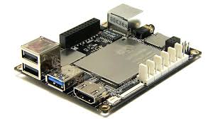
LattePanda is an x86/x64 SBC with a quad-core Intel Atom x8300 “Cherrytrail” processor that can run Windows 10. It includes either 2GB or 4GB of RAM, integrated Bluetooth 4.0 and 802.11 n WiFi, 1 x USB 3.0, 2 x USB 2.0, HDMI out and an integrated ATMega32u4 co-processor - like you would find in an Arduino Leonardo - with accompanying GPIO - all on one palm-sized board!
This unique setup makes LattePanda ideal for a number of user scenarios. In this tutorial will focus on the advantages of LattePanda’s integrated microcontroller. When this microcontroller is used in conjunction with the Intel Atom processor, you can use physical inputs to interface with software in real time. This makes it a useful tool interaction design projects.
Hardware
LattePanda - A Powerful Windows 10 Mini PC 2GB/32GB
10k Potentiometer
Jumper Wires
Software
Standard Firmata
vvvv
Here I have opted to use a LattePanda, with 2GB of ram and an x86 architecture. Note that it is also possible to use a LattePanda Enhanced (4GB RAM, x64 architecture), but you will need to use the 64-bit version of vvvv if you do. Because of the LattePanda’s Arduino co-processor setup, we can handle all of this using just one board, without any external microcontrollers!
Work Area
As LattePanda ships with a full version of Windows 10 Home edition preinstalled, so it is quite possible to carry out this entire tutorial on it using a USB keyboard and mouse and an HDMI monitor.
If you don’t have spare keyboards, mice and monitors, you might also consider using a VNC or remote desktop solution such as TeamViewer. You can find instructions on how to set up a VNC in Windows on the LattePanda website.
Method
Upload Firmata to the Microcontroller
First I need to upload the Firmata protocol to the Arduino microcontroller. This will allow the software on the Intel processor to communicate with the Arduino microcontroller.
Go in to Arduino IDE. I used verion 1.7.9.
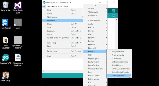
Go to File > Examples > Firmata and select “Standard Firmata”. This will open an Arduino sketch.
Select Tools > Board and select “Arduino Leonardo”

Select the COM port associated with the Arduino microcontroller.
Upload it.
It is beyond the scope of this tutorial to show you how to upload to an Arduino, so if you are not sure how google it (or Baidu it if you are in China like I am), it’s not that hard. This is the only “traditional” line-based code we will be using for this project, so that’s good news for you if code intimidates you.
Install vvvv
Boot in to Windows on your LattePanda and point your browser to https://vvvv.org/downloads.
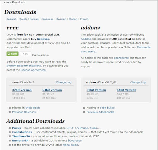
Download vvvv and the addon pack. Make sure you install the correct version for your system architecture – 32 bit for LattePanda Standard and 64 bit for LattePanda Enhanced. I am using a LattePanda Standard, so I will select the 32-bit version of vvvv.
Just to make sure you don’t miss this part, you will also need to install the add-on pack to your vvvv installation folder for this project to work properly. This is because the addon pack includes the vvvv’s firmata plugin.
To install the addon pack, simply unzip the archive directly to your vvvv installation folder so that the “girlpower”, “lib” and “licences” folders merge together. That’s all!
Using vvvv
Next, open vvvv. On the first start you will be greeted with a series of green and red boxes. This is to make sure you have all the correct tools installed on your system to run vvvv properly. Click through all the options until all the boxes are green. You will probably need to download a few extra components but the software handles the process automatically.
When all this is completed you will be able to get in to vvvv’s interface. The interface is very minimalist and works a little different to a regular Windows application.
The vvvv Interface
The key thing to know is that a middle click will bring up the menu where you can load, save, and a whole bunch of other things. Programming is done visually by dragging and dropping boxes (called nodes) on to the interface and connecting them together with lines. You can change the properties of slices by pressing CTRL + I to bring up a properties panel (“Herr Inspektor”, which is German for “Mr Inspector” - the properties inspector where you can change each node’s parameters).
vvvv Terminology
The vocabulary of vvvv is potentially confusing for beginners so here are some basic explanations that I have taken from vvvv's documentation.
A node is a block that you can connect to other blocks to create different behaviors
A spread is a one dimensional list (array) of data
A slice is one element of a spread
A slice count/spread count is the number of slices in a spread (sometimes used synonymously).
An index is a number referencing a slice via its position in a spread, counting from 0.
In the same way that Arduino IDE calls its files “sketches”, vvvv calls its files “patches”.
Once you get the hang of the basic interface and various terminologies, vvvv becomes far less intimidating. I recommend taking a moment to play around and familiarize yourself with the interface before moving forward.
Luckily, for the next section most of the work has been done for us already. All we will do is tweak a pre-existing file to implement the behavior we want.
Open your vvvv installation folder. Navigate to girlpower > IO > Arduino and open “0_Arduino_UsingFirmata”. This will open a patch file.
Save it to a new location by middle clicking, selecting save as, and select a preferred location. Now you can edit the file without changing the original.
Next delete the parts that aren’t needed. Click and drag a square to select multiple nodes.
Delete the large section of text as we won’t need it.
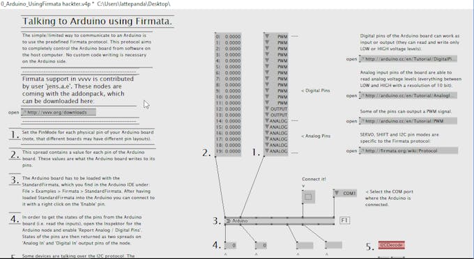
We will also not be using i2c for this project, so we can delete that section.
Also delete the two boxes of text at the bottom.
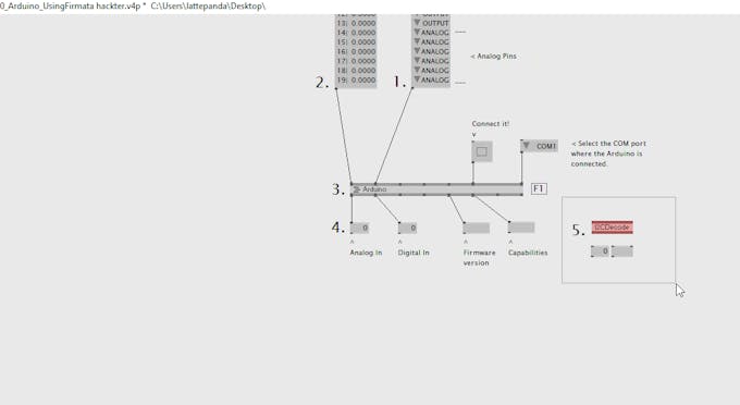
Select the COM port that your Arduino is communicating on.
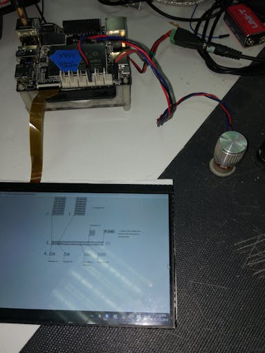
I have used a 10k potentiometer to give an analog input. I have connected it to the LattePanda’s 3 pin analog interface on digital pin 11. (This three pin interface also gives me convenient power and ground rails!)

A Quick Note on Potentiometers
Potentiometers (aka: pots; wipers; variable resistors) have 3 pins. The left and right pins will be power or ground. The middle pin will be your analog signal. You can swap the start and end of your potentiometer’s range by reversing the potentiometer’s polarity, but the analog signal will always be the middle pin. Now you know!
Make your Patch!
Generating Values
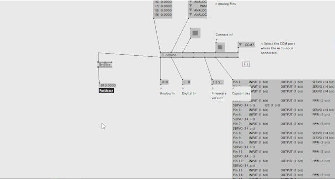
Next, we need to set this up in software. In vvvv go to the Arduino node find the “analog in” handle and left click and drag a line from it, and then middle click to create a IOBox where you can enable analog pin reporting.
Make sure it is connected to the analog pin that your pot is connected to.
You will be dealing with a spread of 6 slices. Since your pot is connected to the 1st analog pin, you will have 6 slices but only want the 1st one.
Double left click to bring up the search for a module and search for get slice (spreads).
The input pin is the spread, so connect it to your pot pin – connect analog in on Arduino to analog in on the node.
Take the output, middle mouse click and you will see your pot’s analog value.
Name it in Herr Inspektor (ctrl+I to bring up) “potentiometer”.
Now you can turn your pot. The value should go from 0 all the way to 1023. If it goes from 1023 – 0 you can reverse your pot’s polarity to change it if you wish.
To make this useable in vvvv we need to map it back to a value between 0 and 1.
Do this by using a map node. Double left click and search for “map(value)”.
Connect it to the input. Press ctrl I to bring up Herr Inspektor.
For our map value, the source minimum is 0 and the source maximum is 1023. The destination minimum is 0 and the destination maximum is 1
Using Values To Generate Activities
Next we will rotate a quad
Double left click and search renderer ex9
place it on your workspace.
Select it and press alt+2 to dock it in place.
You can also change its size or make it full screen by pressing alt+enter
Double left click and type quad
Select quad dx9
Double click and select transform 2d node, and connect this to the quad.

Hook the mapped value you made earlier to the rotation pin of your transform node. You should now be able to rotate your potentiometer to rotate the quad! Cool!
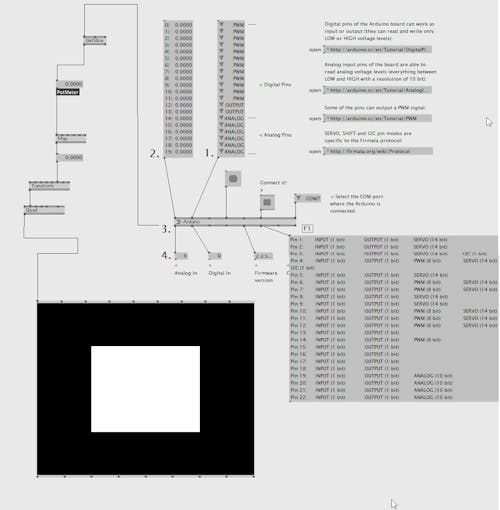
Here is a full picture of my patch incase you got stuck:
Conclusion
This simple project gives you a starting point for leveraging this small but powerful computer. You can build on this project in several ways. Why not try adding more analog inputs to control extra parameters? Try rotating a 3D object instead of a 2D one.
For fun, try hooking up the transform pins to other pins on the quad node. You can scale your quad along its x, y axes while simultaneously rotating it for zoom in rotating effects. Remember you can make the renderer full screen if you press alt + enter. Make a cool interactive installation at parties and social gatherings. Swap out the potentiometer for other analog sensors, such as a distance sensor.
With Windows and an Arduino integrated on the same board, LattePanda is a powerful tool for interactive designers. You can take inputs from sensors and process them in real time for amazing interactive effects. If you like vvvv, check out Processing or MaxMSP.
You can get all the components you need in any Arduino Starter kit, such as this one. This includes a range of sensors and actuators that are directly compatible with LattePanda and Arduino. Highly recommended!
Notes
Sometimes you will need to refresh the serial ports for vvvv to work with your components as vvvv doesn’t always do this. Try banging the “connect it” or “report analog pins” boxes (or by changing their value from 1 – 0 and 0 – 1)
There is lots of scope for improvement, and I would love to hear about it if you try! Let me know in the comments or post on the LattePanda forum.
DON’T FORGET TO TINKER!
References
Firmata, Arduino and VVVV, an introduction
https://vvvv.org/documentation/spread-definitions
SCHEMATICS
Full Patch
Here is my patch if you get lost...
If you have questions, please ask!

CODE
/*
  Copyright (C) 2006-2008 Hans-Christoph Steiner.  All rights reserved.

  This library is free software; you can redistribute it and/or
  modify it under the terms of the GNU Lesser General Public
  License as published by the Free Software Foundation; either
  version 2.1 of the License, or (at your option) any later version.

  See file LICENSE.txt for further informations on licensing terms.
 */

/*
 * TODO: add Servo support using setPinMode(pin, SERVO);
 * TODO: use Program Control to load stored profiles from EEPROM
 */

#include <EEPROM.h>
#include <Firmata.h>

/*==============================================================================
 * GLOBAL VARIABLES
 *============================================================================*/

/* analog inputs */
int analogInputsToReport = 0; // bitwise array to store pin reporting
int analogPin = 0; // counter for reading analog pins

/* digital pins */
byte reportPINs[TOTAL_PORTS];   // PIN == input port
byte previousPINs[TOTAL_PORTS]; // PIN == input port
byte pinStatus[TOTAL_DIGITAL_PINS]; // store pin status, default OUTPUT
byte portStatus[TOTAL_PORTS];

/* timer variables */
extern volatile unsigned long timer0_overflow_count; // timer0 from wiring.c
unsigned long nextExecuteTime; // for comparison with timer0_overflow_count


/*==============================================================================
 * FUNCTIONS
 *============================================================================*/

void outputPort(byte portNumber, byte portValue)
{
  portValue = portValue &~ portStatus[portNumber];
  if(previousPINs[portNumber] != portValue) {
        Firmata.sendDigitalPort(portNumber, portValue);
        previousPINs[portNumber] = portValue;
        Firmata.sendDigitalPort(portNumber, portValue);
    }
}

/* -----------------------------------------------------------------------------
 * check all the active digital inputs for change of state, then add any events
 * to the Serial output queue using Serial.print() */
void checkDigitalInputs(void)
{
    byte i, tmp;
    for(i=0; i < TOTAL_PORTS; i++) {
        if(reportPINs[i]) {
            switch(i) {
            case 0: outputPort(0, PIND &~ B00000011); break; // ignore Rx/Tx 0/1
            case 1: outputPort(1, PINB); break;
            case ANALOG_PORT: outputPort(ANALOG_PORT, PINC); break;
            }
        }
    }
}

// -----------------------------------------------------------------------------
/* sets the pin mode to the correct state and sets the relevant bits in the
 * two bit-arrays that track Digital I/O and PWM status
 */
void setPinModeCallback(byte pin, int mode) {
    byte port = 0;
    byte offset = 0;

    if (pin < 8) {
      port = 0;
      offset = 0;
    } else if (pin < 14) {
      port = 1;
      offset = 8;
    } else if (pin < 22) {
      port = 2;
      offset = 14;
    }

    if(pin > 1) { // ignore RxTx (pins 0 and 1)
        pinStatus[pin] = mode;
        switch(mode) {
        case INPUT:
            pinMode(pin, INPUT);
            portStatus[port] = portStatus[port] &~ (1 << (pin - offset));
            break;
        case OUTPUT:
            digitalWrite(pin, LOW); // disable PWM
        case PWM:
            pinMode(pin, OUTPUT);
            portStatus[port] = portStatus[port] | (1 << (pin - offset));
            break;
        //case ANALOG: // TODO figure this out
        default:
            Firmata.sendString("");
        }
        // TODO: save status to EEPROM here, if changed
    }
}

void analogWriteCallback(byte pin, int value)
{
    setPinModeCallback(pin,PWM);
    analogWrite(pin, value);
}

void digitalWriteCallback(byte port, int value)
{
    switch(port) {
    case 0: // pins 2-7 (don't change Rx/Tx, pins 0 and 1)
        // 0xFF03 == B1111111100000011    0x03 == B00000011
        PORTD = (value &~ 0xFF03) | (PORTD & 0x03);
        break;
    case 1: // pins 8-13 (14,15 are disabled for the crystal)
        PORTB = (byte)value;
        break;
    case 2: // analog pins used as digital
        PORTC = (byte)value;
        break;
    }
}

// -----------------------------------------------------------------------------
/* sets bits in a bit array (int) to toggle the reporting of the analogIns
 */
//void FirmataClass::setAnalogPinReporting(byte pin, byte state) {
//}
void reportAnalogCallback(byte pin, int value)
{
    if(value == 0) {
        analogInputsToReport = analogInputsToReport &~ (1 << pin);
    }
    else { // everything but 0 enables reporting of that pin
        analogInputsToReport = analogInputsToReport | (1 << pin);
    }
    // TODO: save status to EEPROM here, if changed
}

void reportDigitalCallback(byte port, int value)
{
    reportPINs[port] = (byte)value;
    if(port == ANALOG_PORT) // turn off analog reporting when used as digital
        analogInputsToReport = 0;
}

/*==============================================================================
 * SETUP()
 *============================================================================*/
void setup()
{
    byte i;

    Firmata.setFirmwareVersion(2, 0);

    Firmata.attach(ANALOG_MESSAGE, analogWriteCallback);
    Firmata.attach(DIGITAL_MESSAGE, digitalWriteCallback);
    Firmata.attach(REPORT_ANALOG, reportAnalogCallback);
    Firmata.attach(REPORT_DIGITAL, reportDigitalCallback);
    Firmata.attach(SET_PIN_MODE, setPinModeCallback);

    portStatus[0] = B00000011;  // ignore Tx/RX pins
    portStatus[1] = B11000000;  // ignore 14/15 pins
    portStatus[2] = B00000000;

//    for(i=0; i<TOTAL_DIGITAL_PINS; ++i) { // TODO make this work with analogs
    for(i=0; i<14; ++i) {
        setPinModeCallback(i,OUTPUT);
    }
    // set all outputs to 0 to make sure internal pull-up resistors are off
    PORTB = 0; // pins 8-15
    PORTC = 0; // analog port
    PORTD = 0; // pins 0-7

    // TODO rethink the init, perhaps it should report analog on default
    for(i=0; i<TOTAL_PORTS; ++i) {
        reportPINs[i] = false;
    }
    // TODO: load state from EEPROM here

    /* send digital inputs here, if enabled, to set the initial state on the
     * host computer, since once in the loop(), this firmware will only send
     * digital data on change. */
    if(reportPINs[0]) outputPort(0, PIND &~ B00000011); // ignore Rx/Tx 0/1
    if(reportPINs[1]) outputPort(1, PINB);
    if(reportPINs[ANALOG_PORT]) outputPort(ANALOG_PORT, PINC);

    Firmata.begin();
}

/*==============================================================================
 * LOOP()
 *============================================================================*/
void loop()
{
/* DIGITALREAD - as fast as possible, check for changes and output them to the
 * FTDI buffer using Serial.print()  */
    checkDigitalInputs();
    if(timer0_overflow_count > nextExecuteTime) {
        nextExecuteTime = timer0_overflow_count + 19; // run this every 20ms
        /* SERIALREAD - Serial.read() uses a 128 byte circular buffer, so handle
         * all serialReads at once, i.e. empty the buffer */
        while(Firmata.available())
            Firmata.processInput();
        /* SEND FTDI WRITE BUFFER - make sure that the FTDI buffer doesn't go over
         * 60 bytes. use a timer to sending an event character every 4 ms to
         * trigger the buffer to dump. */

        /* ANALOGREAD - right after the event character, do all of the
         * analogReads().  These only need to be done every 4ms. */
        for(analogPin=0;analogPin<TOTAL_ANALOG_PINS;analogPin++) {
            if( analogInputsToReport & (1 << analogPin) ) {
                Firmata.sendAnalog(analogPin, analogRead(analogPin));
            }
        }
    }
}
Recent Blogs

Run Qwen2.5 on Raspberry Pi 5 using Ollama
This article will explore how to install and run Qwen2.5 on a Raspberry Pi 5 using the Ollama runtime framework.
REVIEWS Raspberry Pi Dec 11 2024

Run Gemma2 on Raspberry Pi 5 using Ollama
In this article, we will delve into the process of installing and running the SLM(small language model) Gemma2 on the Single Board Computer (SBC) Raspberry Pi 5 using the Ollama runtime framework.
REVIEWS Raspberry Pi Dec 11 2024

Run phi3.5 on Raspberry Pi 5 using Ollama
In this write-up, we delve into the process of installing and executing phi3.5-3.8b on a Raspberry Pi 5, leveraging the Ollama runtime framework.
REVIEWS Raspberry Pi Dec 09 2024