Introduction
Digital potentiometer is also called "Digital Pot" in short. It is a kind of mixed signal IC, which is able to dynamically change the internal resistors through MCU like Arduino. Compared to the traditional mechanical potentiometer, the digital pot features as flexible (program control), small size (ICs) and high reliability (without mechanical parts). It can replace the tradition one in many applications. Digital pot is usually used to change the sound volume in audio devices, such as smart loudspeaker, cell phone, and music player. In addition, with a proper design op-amp circuit, the digital pot can also be applied to change some key parameters of the circuit dynamically, such as LED DC dimming (output current), linear stable voltage source (output voltage), oscillator (frequency and amplitude), low pass filter (bandwidth) and differential amplifier (gain).
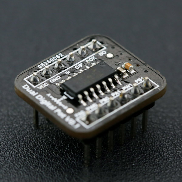
This breakout employs MCP42100 internally manufactured with two individual 100K digital pot POT0 and POT1. Each pot has 256 taps with a resistor of 100KΩ. It supports wide voltage supply (DC 2.7V - 5.5V) compatible with MCU of 3.3V and 5V. The breakout features as small size (20.0mm*18.0mm) and reserves the SO pin for multiple breakouts being configured in daisy-chain connection. If you have a I/O shield in hand, this breakout can be easily connected to it with the attached 5 pin male to male cable.
Specification
- Supply Voltage: 2.7~5.5V DC
- Static Operation Current: < 1 μA
- Potentiometer Value: 100 KΩ
- Resolution: 8 bits, 256 taps for each potentiometer
- Number of Potentiometers: 2
- Interface: SPI
- Operation Temperature: -40℃~85℃
- Dimension: 20.0mm*18.0mm
Pin Definition
| Pin | Description |
|---|---|
| VCC | Power supply (DC 2.7V - 5.5V) |
| GND | Ground |
| SI | Serial data input |
| CS | Chip select |
| SCK | Serial clock input |
| SO | Serial data output |
| PAx | Potentiometer terminal A (x=0,1) |
| PBx | Potentiometer terminal B (x=0,1) |
| PWx | Potentiometer wiper terminal (x=0,1) |
NOTE: 1. Resistor terminals A, B and W have no restrictions on polarity with respect to each other.
2. Current through terminals A, B and W should not excceed ±1mA.
3. Voltages on terminals A, B and W should be within 0 - VCC.
Tutorial
This tutorial generates two triangular waves out of phase by the dual digital pot to demonstrate its basic usage. The two internal digital pot POT0 and POT1 server as voltage divider with terminal A connected to VCC and terminal B connected to GND. We use Arduino UNO R3 to control the terminal W0 of POT0 to change it from min to max (Dn: 0 -> 255) every 1 ms and then in reverse, from max to min (Dn: 255 -> 0). On the contrary, the terminal W1 of POT1 will be changed from max to min (Dn: 255 -> 0) every 1 ms and then in reverse, from min to max (Dn: 0 -> 255). Two channels CH1 and CH2 of the oscilloscope will be used to observe the voltage of W0 and W1 respectively to check whether all the possible taps are available.
Basic Principle
This breakout employs MCP42100, which has two individual digital potentiometer POT0 and POT1 corresponding to two groups of terminals A0, B0, W0 and A1, B1, W1. Similar to the mechanical potentiometer, terminal A and B can be taken as two pins of a resistor (the nominal resistance is Rab=100KΩ) while terminal W is the wiper. The wiper can be changed to one of the 256 positions evenly distributed between A and B. The wiper is reset to the mid-scale position (Dn=128,0x80) upon power-up.

To change the position of the wiper W, two byte should be sent. The first byte is the command to determine which pot to be selected. The second byte is the data to determine the position of the wiper. This byte is also denoted as Dn. When Dn=0, terminal B is connected to W. When Dn=255, W is changed to the closest position to A. For example, to set W0 of POT0 to the position of 100, Arduino should first sends 0x11 (Write data, select POT0) and then 0x64 (=100, decimal) through the SPI.


- The resistance of each digital pot can be calculate by the equations below.

Requirements
-
Hardware
- DFRduino UNO Mainboard (or similar) x 1
- Bread board x 1
- IO Expansion Shield for Arduino V7.1 (optional) x 1
- Analog Cable (5Pin male to male) x 1
-
Software
- Arduino IDE (Version requirements: V1.8.x), Click to Download Arduino IDE from Arduino®
Hardware Connection
The module can be connected to Arduino with the attached 5 pin male-to-male cable (one end bonded together and the other end separated ). Insert the breakout into the breadboard and plug the cable with the bonded end to the breadboard where pin VCC, GND, SI, CS, SCK lie on (leave pin SO unconnected). The individual end inserts into Arduino shown as follow.


Sample Code
If the IO Expansion Shield is used for connection, the sentence "const int CS_PIN = 10;" should be change to "const int CS_PIN = 4;" in the sample code. Because the SS pin in the SPI interface of the shield connects to D4 internally.
Experiment Results
Two triangular waves out of phase can be observed from the oscilloscope. If we zoom in a section of the wave, the triangular wave is actually made up of many steps. Each steps correspond to one wiper position. The width of the step is about 1ms, because the program delay for 1ms between every wiper changes. The upstairs half cycle and the downstairs half cycle consist of 256 steps each, therefore the period of the triangular wave is 256*2=512ms. The digital pot can quickly change the wiper position and the settling time can up to micro seconds (18μs, typical).

Template Code for MCP42100
A template code is provided here for user to learn how to control the MCP42100 dual digital pot.
FAQ
For any questions, advice or cool ideas to share, please visit the DFRobot Forum.