Introduction
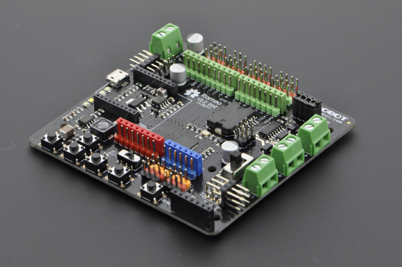
RoMeo V2[R3]is an All-in-One Arduino compatible microcontroller especially designed for robotics applications from DFRobot. The Romeo benefits from the Arduino open source platform, it is supported by thousands of open source codes, and can easily be expanded with Arduino Shields. The integrated 2 way DC motor driver and Xbee socket allows you to start your project immediatly without the need for an additional motor driver or wirless shield.

The analog sensor port pin mapping on RoMeo v2 is different from the version before. Be careful to wire your sensor or other devices correctly or the wrong power connection would destroy your device.
Please Turn OFF the Motor Power Switch when debugging Romeo through USB cable. Or the external power supply(>12V) will destroy your Romeo.
Please select Leonardo board when uploading a sketch by Arduino IDE.
Serial port 0 or 1 Read more from Arduino.cc: Please use Serial1.***() instead of Serial.***() in code to communicate with devices connected to serial interface, i.e. Pin 0/1. e.g. Bluetooth, WiFi module, Xbee etc. Serial.***() is for USB debugging on pc serial monitor.
Analog 0: If you are going to use the Analog port 0, you have to pay attention to the switch(s1-s5), turn it OFF please. There are five buttons connected to A0, if you turn ON the button switch,then the A0 read value would be not the one you want.
Specification
| Basic | Feature | Improvement compared with Romeo v1.1 |
|---|---|---|
| DC Supply:USB Powered or External 6V~23V DC |
DC Output:5V(200mA) / 3.3V(100mA)
Motor driver Continuous Output Current:2A
Microcontroller:ATmega32u4
Bootloader: Arduino Leonardo
Serial Interface
TTL Level(Serial1.***();)
USB(Serial.***())
Size:89x84x14mm |
Compatible with the Arduino R3 pin mapping
Analog Inputs: A0-A5, A6 - A11 (on digital pins 4, 6, 8, 9, 10, and 12)
PWM: 3, 5, 6, 9, 10, 11, and 13. Provide 8-bit PWM output
5 key inputs for testing
Auto sensing/switching external power input
Support Male and Female Pin Header
Built-in Xbee socket
Integrated sockets for APC220 RF Module and DF-Bluetooth Module
Three I2C/TWI Interface Pin Sets(two 90°pin headers)
Two way Motor Driver with 2A maximum current |
Wide operating input voltage
Directly support Xbee and XBee form factor wifi,bluetooth and RF modules
ON/OFF switch to control the system power from extermal motor power
3 Digital I/O extension(D14-D16)
S1-S5 switch replace jump cap
Micro USB instead of A-B USB connector
Analog sensor extension port: Orange for Signal,Red for Vcc,Black for GND |
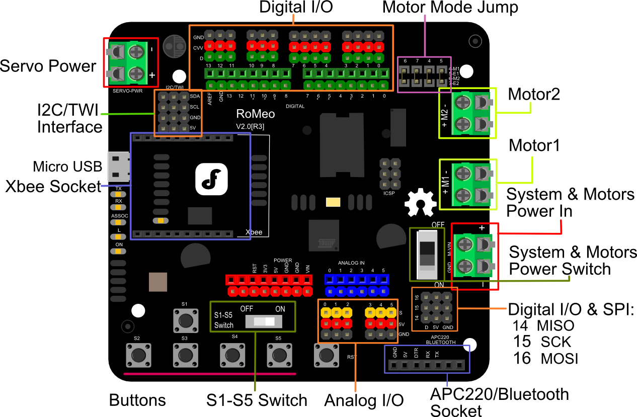
RoMeo V2 Pinout
Power solution design
This motor controller power solution is specially designed for the robotics application.
Servo Power terminal
- It integrated an external servo power terminal. The range of this power input is about 5~12v. We recommend you to use 5v. So the servo power supply extension won't break the digital sensors connected to the 3p digital sensor interface. However,for driving 6~12v servos with the voltage input higher than 5v, it's not available to extend 5v sensor on all the digital sensor interface anymore.
- The servo power terminal won't supply system working voltage.
Motor Power terminal
The setting for the system & motor power switch:
- On: supply power to the motor driver and system power regulator. The input range is from 5~23 volts. It's suitable for most of robot platform.
- Off: Isolate the system power supply from the motor power. In this case, it requires to supply system voltage from Micro USB port,5v power source to 5v & GND pins directly or 5~23v power source to VIN & GND pins.
Example use of Button S1-S5
Pin Allocation
| Pin | Function |
|---|---|
| Digital 4 | Motor 1 Direction control |
| Digital 5 | Motor 1 PWM control |
| Digital 6 | Motor 2 PWM control |
| Digital 7 | Motor 2 Direction control |
"PWM Mode"
| Pin | Function |
|---|---|
| Digital 4 | Motor 1 Enable control |
| Digital 5 | Motor 1 Direction control |
| Digital 6 | Motor 2 Direction control |
| Digital 7 | Motor 2 Enable control |
"PLL Mode"
PWM Control Mode

The PWM DC motor control is implemented by manipulating two digital IO pins and two PWM pins. As illustrated in the diagram above (Figure 5), Pin 4,7 (7,8 for old Romeo version) are motor direction control pins, Pin 5,6 (6,9 for old Romeo version) are motor speed control pins.
Sample Code:
PLL Control Mode
The Romeo also supports PLLPhase locked loop control mode.

Sample Code:
FAQ
For any questions, advice or cool ideas to share, please visit the DFRobot Forum.