Introduction
URM04 is developed based upon our popular URM37 ultrasonic sensor. The RS485 interface allows a number of sensors working together. Up to 32 URM04 may be connected together in a network.
A. Please read this mannual carefully before power on the device.
B. Do not use this device for military or medical purpose as they are not designed to.


Specification
- Power: +5V
- Current: <20mA
- Working temperature: -10℃~+70℃
- Detecting range: 4cm-500cm
- Resolution: 1cm
- Frequency: 40KHz
- Interface: RS485
- Units: Range reported in cm
- Temperature sensor: 12 bits reading from serial port
- Size: 34mm × 51 mm
- Weight: 30g
- Default Address:0x11
- Default Baudrate:19200
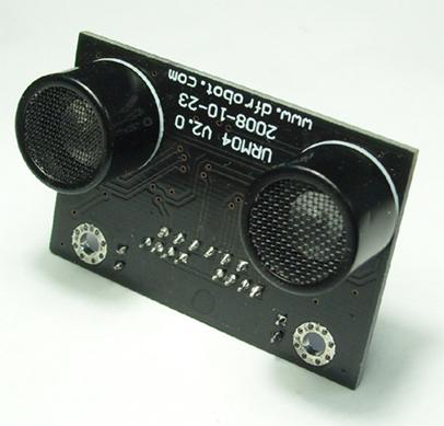
Dimension and Pin definition
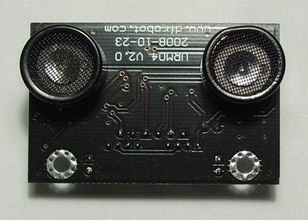
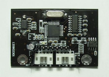
- RS485 Interface:Two connectors
- +: +5V DC Power +5V
- -: GND Ground
- A: A RS485 A(+)
- B: B RS485 B(-)
- ISP Pin: For factory firmware uploading
- Communication LED: As the device is powered up, this LED will flash four times which indicates that the sensor is working properly. This LED will also flash when it is communcating with other devices.
- Jumper A: Not in use
- Jumper B: When the sensor is working under a network, only the Jumper B for the first Device and the last Device need to be bridged.
Communication Protocols
The device is fixed at 19200 bps Baud Rate,8/N/1.
Note:The previous version has 115200 bps Baud Rate,8/N/1.
Set Device Address
Command:
| Header | Cmd | Length | Cmd | Set Address | SUM |
|---|---|---|---|---|---|
| 55 | aa | AB | 1 | 55 | ADD |
Return Value:
| Header | Address | Length | Cmd | Flag | SUM |
|---|---|---|---|---|---|
| 55 | aa | ADD | 1 | 55 | S |
TIPs: The address of each device can be changed when multiple devices are connected. The new Address must be between 0x11 and 0x80. If the address is set sucessfully, the flag will be set to 0x01 in the return data. If unsucessful, there is no return data. (The default address for the sensor is 0x12)
Note: The previous default address is 0x11.
Example:
Command:
0x55 0xaa 0xab 0x01 0x55 0x12 0x12 (Set Address to 0x12)
Return:
0x55 0xaa 0x12 0x01 0x55 0x01 0x69 (Address set sucessfully)
Trigger measurement
Command:
| Header | Address | Length | Cmd | SUM |
|---|---|---|---|---|
| 55 | aa | AD | 0 | 01 |
Return Value:
None
TIPs: Trigger one measure. The distance data will be available after 30ms. This command do not return any data. The distance data is stored in the buffer, and the Read Distance command can be applied to get this distance data.
Example:
Command:
0x55 0xaa 0x00 0x01 0x00
Return:
-
None
Read Distance
Command:
| Header | Address | Length | Cmd | SUM |
|---|---|---|---|---|
| 55 | aa | ADD | 0 | 02 |
| Header | Address | Length | Cmd | High Byte | Low Byte | SUM |
|---|---|---|---|---|---|---|
| 55 | aa | ADD | 2 | 02 | H | L |
TIPs: The command will return the measured distance value. The value consists of two bytes. If the measurment is out of range or unsucessful, the return data will be “0xFF(H) 0xFF(L)”.
Example:
Command:
0x55 0xaa 0x11 0x00 0x02 0x12(SUM)
Return:
0x55 0xaa 0x11 0x02 0x02 0x01 0x0A 0x11 (Distance is 266 cm) <br> 0x55 0xaa 0x11 0x02 0x02 0xFF 0xFF 0x1F (Out of Range)
Read tempeature
Command:
| Header | Address | Length | Cmd | SUM |
|---|---|---|---|---|
| 55 | aa | ADD | 0 | 03 |
| Header | Address | Length | Cmd | High Byte | Low Byte | SUM |
|---|---|---|---|---|---|---|
| 55 | aa | ADD | 2 | 03 | H | L |
TIPs: The command will return the temperature reading. The return temperature reading is using Celsius scale. If the temperature is above 0 Celsius, the first four bits of High will be all 0. If the temperature is below 0 Celsius, the first four bits of High will be all 1. The last 4 bits of High together with the Low bits stands for 12bits temperature. The resolution is 0.1. When the reading is invalid, it returns 0xFF 0xFF
Example:
Command:
0x55 0xaa 0x11 0x00 0x03 0x13(SUM)
Return:
0x55 0xaa 0x11 0x02 0x03 0xF0 0x0A 0x11 (+1 Celsius Degree)<br> 0x55 0xaa 0x11 0x02 0x03 0x00 0x0A 0x20 (-1 Celsius Degree)<br> 0x55 0xaa 0x11 0x02 0x03 0xFF 0xFF 0x20 (Out of Range)
Function to calculate the temperature:
Sensor Connection Diagram
As the sensor uses RS485 interface which can not be connected directly to the MCU, a MAX485 chip will bridge the TTL interface to RS485, as shown in Figure 4.
For PC users, either a USB-RS485 or RS232-RS485 converter will bridge the gap. A diagram is depicted in Figure 5 and 6.


Sensor Networking
Upto 32 URM04 sensors are able to join a network. Simply serially connect the sensors uses twisted pair cables. A diagram is illustrated in Figure 7.

Arduino sketch for driving one URM04 sensor
The sketch code:
The library code: please place the library file Urm4parser.h in to the sketch folder.