Introduction
It's nearly Christmas!! Sick of boring old Christmas tree lights? Why not use one of our RGB LED strips for your Christmas tree?
DFRobot RGB LED strips come in 3 meter lengths and include a silicon rubber waterproof casing. Strips can be cut to any length you wish. Each LED in the strip is individually addressable, and combined with our Bluno microcontroller you can use Bluetooth 4.0 enabled devices to control them, allowing you to control the color and sequence of each LED in the strip.
Using one of our analog sound sensor modules and audio analyzer modules, you can make your own Bluetooth-controlled dancing Christmas lights that will respond to your favorite Christmas tunes.
Let's try them out!
Components
All of these components are included in KIT0069. You can find detailed hardware information about each component by following the Wiki links.
- Bluno arduino Microcontroller v2.0 (SKU: DFR0267)
- I/O Expansion Shield v7.1 (SKU: DFR0265)
- 3m RGB LED Strip (SKU: FIT0352)
- Audio Analyser v2.0 (SKU: DFR0126)
- Analog Sound Sensor v2.0 (SKU: DFR0034)
- F-F Jumper Wires (SKU: FIT0030)
- DC Barrel Jack Adapter - Female (SKU: FIT0151)
- DC Power Supply (5V@3.6A)
Hardware
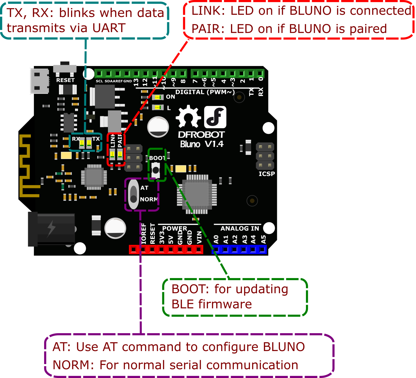
Bluno is an Arduino UNO-based board which integrates a TICC2540 Bluetooth 4.0 chip. It is compatible with Android 4.3+ or IOS 7.0+ devices.
Bluetooth functionality allows:
*Wireless programming via BLE
- Bluetooth HID support
- AT commands for BLE configuration/firmware uploads
Because Bluno is based on an Arduino UNO, it is compatible with all Arduino UNO pins. If you swap out an Arduino UNO-based project for a Bluno board, your Arduino project can go wireless!
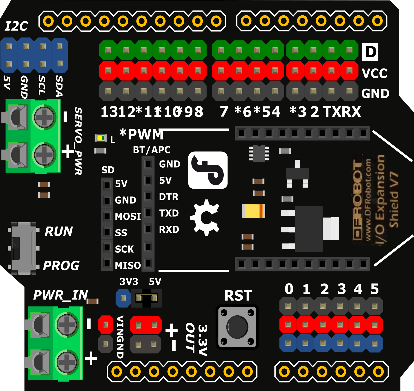
This is an expansion shield for the Arduino UNO. It is compatible with Bluno, Mega2560 or Romeo boards.
For this project it will give us extra I/O pins to connect our RGB LED strip and sound sensor.
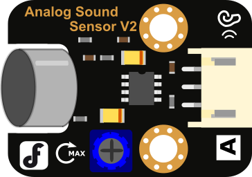
An analog sound sensor is typically used to detect loudness in ambient noise.
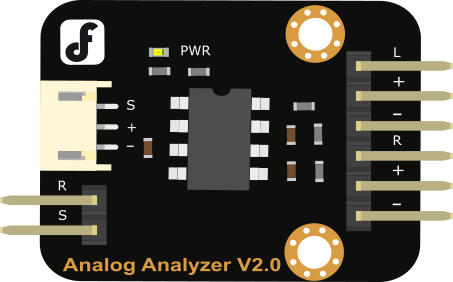
This module, used in combination with an analog sound sensor, will give your micro controller ears. This module features a MSGEQ7 graphic equalizer display filter. It operates by breaking down sound information in to 7 frequency bands where the peak level for each band can be read. The 7 frequencies it measures are: 63Hz, 160Hz, 400Hz, 1kHz, 2.5kHz, 6.25kHz and 16kHz.
Common uses for an audio analyzer include sound visualizers, pattern detection in music or sound activation for a micro controller. For this project we will use it to detect Christmas music.

This is a long strip of RGB LEDS, each containing a tiny WS2812 chip (datasheet). Thanks to the WS2812 chip, every LED in the strip is individually addressable. The strip is 3 meters long and contains 60 LEDs per meter. We recommend using 1 amp of power per meter (3m = 5v@3a). You can cut the strip to any size you wish. Each strip is sheathed in waterproof silicon rubber making it super durable and weatherproof. The LED strip will be the main part of our project.
Connections
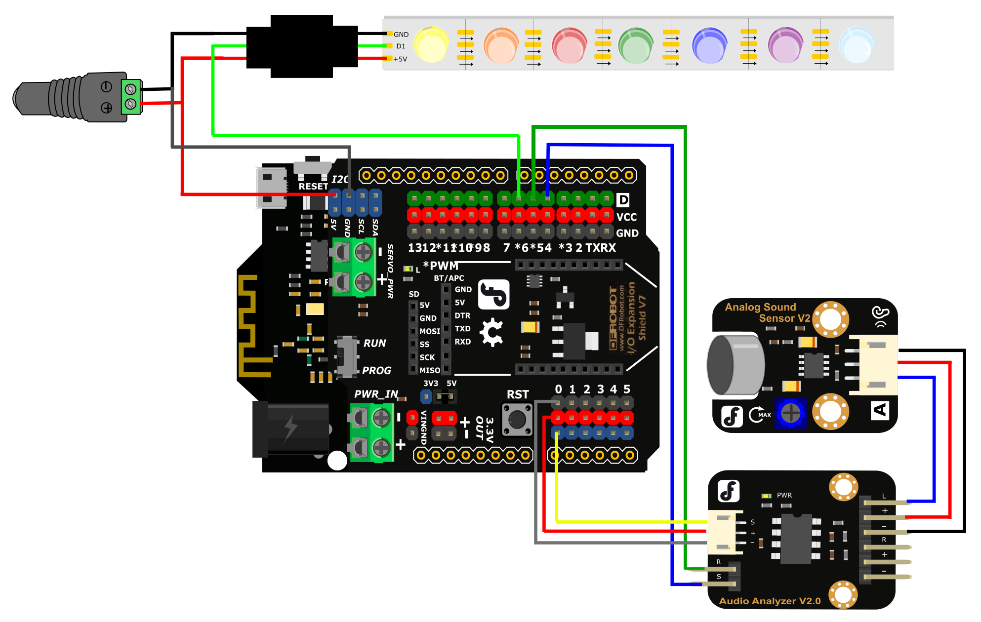
5V@3A is coming from the external power supply to the Bluno and the LED strip via the connector.
The digital signal for the LED strip is provided by digital pin 6 on the Bluno. Use a F-F jumper wire for this.
The audio analyzer module's output is connected to the analog 0 pin on the Bluno. The connector is provided with the module. Make sure that the +, - and s pins are correctly aligned or the circuit will not function.
S on the audio analyzer connects to digital pin 4. Use a F-F jumper wire for this.
RST on the audio analyzer connects to digital pin 5. Use a F-F jumper wire for this.
The analog sound sensor module is connected to the audio analyzer module with the provided connector. Connect the audio analyzer's left channel signal (L), + and - to the analog sound sensor. Make sure that the +, - and s pins are correctly aligned or the circuit will not function.
Software
Sample Sketch
Below is a sample Arduino Sketch that will implement the behavior we want in the hardware.
Expected Behaviour
When the sound sensor is triggered, the entire strip of LED lights will light up in different colors. You will be able to control the colors using our Play BLUno app.
Libraries (IMPORTANT!)
Make sure you download and install the libraries from the product page and install them in the correct directory or the sample sketch will not compile!
On Windows the default directory will be C:\Users\
The following libraries need to be extracted to your Arduino IDE libraries directory:
Color
Adafruit_NeoPixel
AudioAnalyzer
Metro
OneWire
PlainProtocol
Note: Arduino IDE cannot recognize libraries if they are contained in nested folders. Check that each library directory has all necessary files included in a single folder. If library files are in nested folders in the libraries directory, you will have compilation errors when you come to compile your sketch as Arduino IDE will not be able to find your library!
You can check if the libraries have been recognized by opening Arduino IDE and selecting Sketch > Include Library
Scroll down the list and under contributed libraries you should see your libraries listed and ready to use.
Putting It All Together
In Arduino IDE, press the verify button and check that the code can compile. If you get compilation errors, check that the libraries are properly installed.
If all is well, go ahead and upload the code to the Bluno.
When the code is installed, clap your hands or click your fingers near the audio sensor to check if it triggers. Hopefully you will see the LEDs light up in sequence.
The next step is to test the smart device control feature. Open the Play BLUno on your smart device. In the top right corner, tap Search. By default your Bluno will show up as Bluno. (You can change the device name using AT commands if you wish - details here).
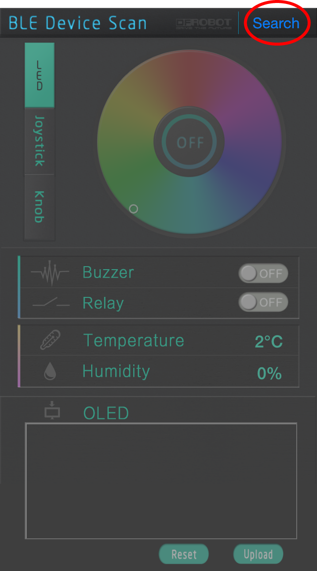
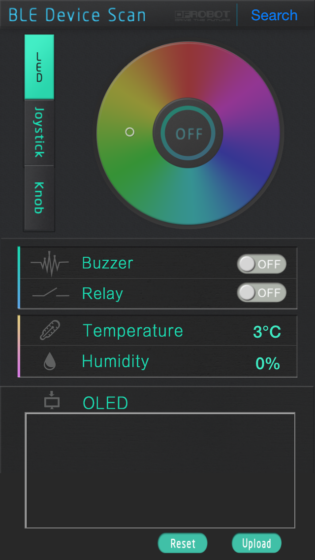
Your smart device will scan for BLE devices in range. When your device shows up, select it and they will pair. You now have a light control interface. Use the color picker to choose the color of the lights.
Cool! Now you have your own set of sound-activated Bluetooth-enabled Christmas lights!
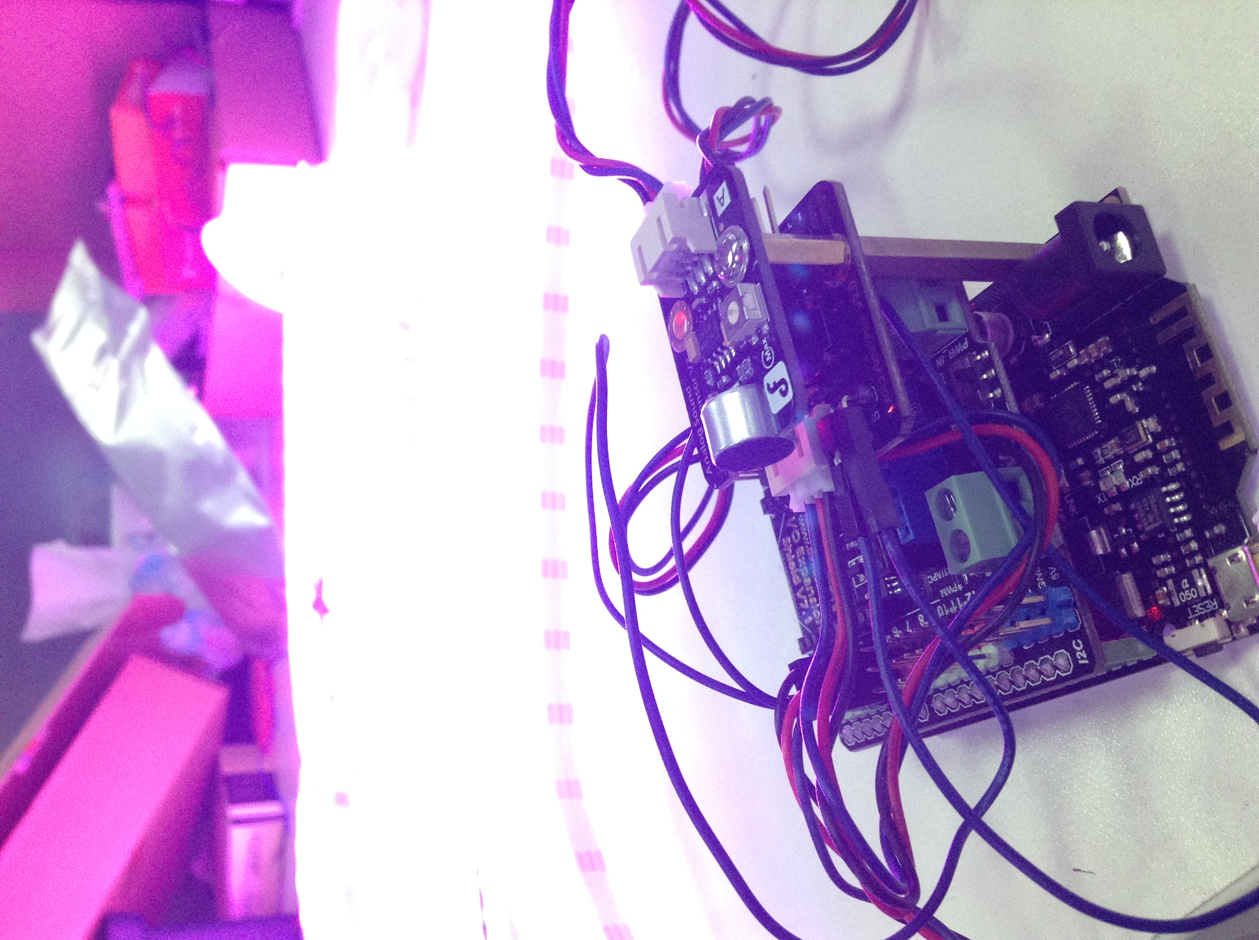
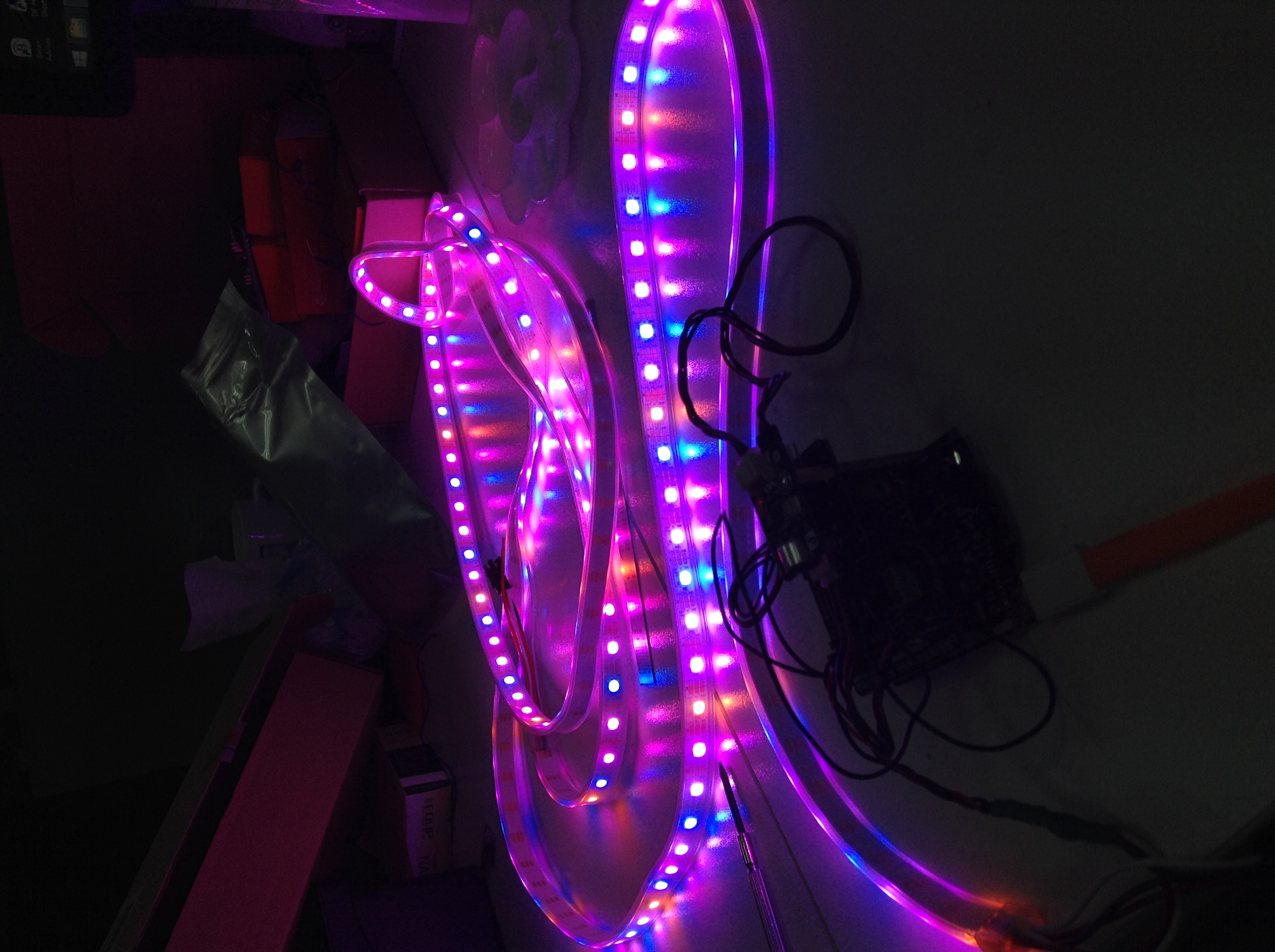
Have a tinker with the sample sketch and see what parameters you can change.
Can you make a different amount of LEDs light up? Can you make the LEDs turn on in a different sequence?
How about alternating LED colors?
What else can you come up with?
FAQ
Q 1. What is the minimum time needed to light up the entire LED strip?
A: 200 LEDs need about 3ms according to our tests.
Q 2. My LED strip turned on yesterday, but will not turn on today. Why?
A: 1) Check your code and circuit connections
2) Check your LED strip has adequate power (5V@3A for 3 meters)
3) If you can find no solution, find the end of the strip connected to your microcontroller. Desolder the -, + and s lines from the end of the LED strip, cut off the end LED and then solder the connections to the next LED along.
Q 3. Are LED strips easily broken?
A: We have tested strips many times with very few issues.