Introduction
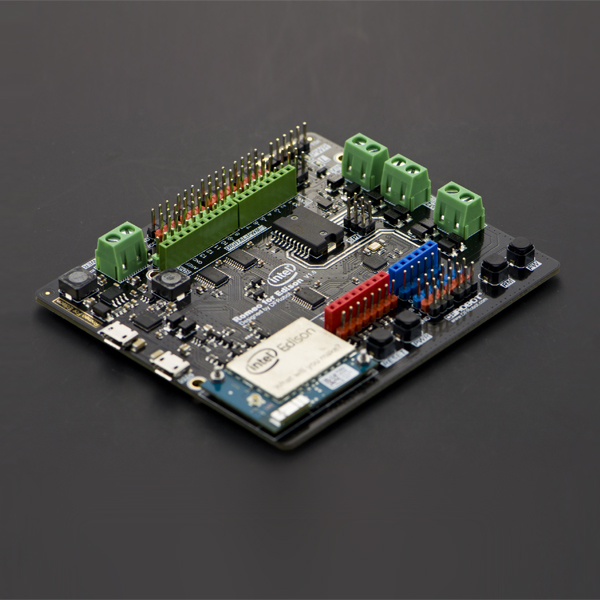
Romeo for Intel Edison is a multi-purpose, all-in-one development platform based on Intel Edison and Arduino SoC. It is especially designed to be useful for robotics applications. Romeo for Intel Edison is compatible with Arduino open source platform and Linux, and supports Java and C development environment. Users are able to extend this platform with thousands of existing shields and modules such as switches, sensors, LEDs, servos, motors easily with Romeo for Intel Edison. It can also be used as a standalone communication platform for software like flash, processing, Max/MSP and VVVV. The integrated 2 way DC motor driver and wireless capability allows you to start your project immediately without the need of any additional motor driver or wireless shield. The Romeo for Intel Edison inherits all functions of the Romeo all-in-one controller by integrating powerful functions the Intel Edison board possesses. You can describe it as a control board specially designed for robotics applications, carrying the powerful gene of Intel Edison and being compatible with Arduino.
| NOTE: According to the Arduino IDE version update and Intel update, the wiki might be out of date, you could visit FAQ for proper solution. |
Specification
| *Microprocessor | :Intel Edison (dual-core processor, 500MHz Intel Atom CPU and 100MHz Intel Quark microcontroller) |
| *Operating Voltage | :5V |
| *Output Voltage | :5V/3.3V |
| *Input Voltage(limits) | :6-20V |
| *Digital I/O pins | :14 |
| *Analog I/O pins | :6 |
| *DC Current per I/O Pin | :10mA |
| *Motor Driver Constant Current | :2 x 2A |
| *Size | :100x88x15mm |
Application
- Digital I/O pins :D0-D13, A0-A5
- PWM Output interface :4 (Digital pins D3, D5, D6 and D9)
- Support USB power and external power supply switch
- Support SPI program port
- Support 1 x I2C interface
- Support 2 way motor drive (Peak Current: 2A)
- Support Broadcom 43340 802.11 a/b/g/n dual band (2.4G and 5GHz) WiFi
- Support Bluetooth 4.0
Pinout Diagram

Tutorial
Romeo for Edison Controller Quick Start
A.The Construction of the Hardware Environment
Part List:
- Romeo for Edison x1
- Edison module x1
- micro USB x1
- Computer x1

Hardware Connection Diagram

B.The Construction of the Software Environment
Operating System
Windows 8.1
Compile Environment
A.Edison Arduion IDE
Download Edison Arduion IDE(winwos version)
Extract to your local folder.
NOTE: There is a bug with Edison Arduion IDE, you have to change your PC location to U.S to avoid IDE FC.Control Panel-->Change data, time or number formats-->Format-->English(United States)

Open Edison Arduion IDE
B.Install Driver
Download FTDI drivers
Install CDM v2.10.00 WHQL Certified.exe


Download Intel Edison Drivers

Install Edison Driver


Open the Device Manager, and check Device Driver

C.Quick test with the module
Open Edison Arduino IDE and open a sample code "Blink"

Select Tools-->Board-->Intel Edison Select Tools-->Serial Port-->COM xx

When the uploading has been finished, the LED will be flashing once a second.

Romeo for Edison Controller Typical Applications
Digital Application
A.LED Blink
Part List and Hardware Connection:
- Micro USB cable x1
- Romeo for Edison Controller x1
- Intel® Edison x1
- Digital Piranha LED light module x1

Sample code: Open Arduino IDE, Select Boards -->Intel Edison and COM port
B.Button Test
Part List and Hardware Connection:
- Micro USB cable x1
- Romeo for Edison Controller x1
- Intel® Edison x1
- Digital Piranha LED light module x1
- Digital Push Button x1

Sample code: Open Arduino IDE, Select Boards -->Intel Edison and COM port
C.Servo Control
Part List and Hardware Connection:
- Micro USB cable x1
- Romeo for Edison Controller x1
- Intel® Edison x1
- Micro Servo x1

Sample code: Open Arduino IDE, Select Boards -->Intel Edison and COM port
NOTE: Only PWM interface could control the Servo.D.Motor Control
Part List and Hardware Connection:
- Micro USB cable x1
- Romeo for Edison Controller x1
- Intel® Edison x1
- Micro Metal Gear Motor x1

Sample code: Open Arduino IDE, Select Boards -->Intel Edison and COM port In this section, please down load the DFRobot_Edison library V1.1 first.
NOTE: The liberaries are still improving;in the event of any divergence between the wiki code and the example in the liberaries ,the liberaries version shall prevail.Analog Application
A.Analog Read
Part List and Hardware Connection:
- Micro USB cable x1
- Romeo for Edison Controller x1
- Intel® Edison x1
NOTE: As Romeo for Edison is using Atmel mega 8 as Analog pins driver. Please download the IIC libary first.
The library is keeping update, so some sample code and picture will be different to the old one.
Sample code: Open Arduino IDE, Select Boards -->Intel Edison and COM port In this section, please down load the DFRobot_Edison library V1.1 first.

Atmega8 Firmware Upgrade
Tools: FTDI programmer x1 Download the Atmega8 firmware V1.2 (The newest firmware V1.1+ fixed IIC communication bug)

FAQ
| Q&A | Some general Arduino Problems/FAQ/Tips |
|---|---|
| Q1 | No Arduino for Edison IDE download link could be found from the link you give, i.e.Intel ... Downloads, and after I finished installing all software, I got newest Arduino IDE 1.6, and there is no place for me to choose Intel to upload Blink.ino, what should I do? |
| A1 | Welcome! You can go to Tools > Board > Boards Manager..., and find Intel i686 Edison, click Install to make it. After you install the needed files, you could see Intel choice. |
| Q2 | Win XP/ Win 7 incompatible issue. |
| A2 | Interl Edison has a compatible issue on Win 7/Win XP, please upgrade your Operating System to Win 8/10. |
| Q3 | My motors lose control/ Analog reading error/ TWI(IIC) communication not good. |
| A3 | It is for the TWI(IIC) issue, please upgrade Atmega8 firmware to the newest version, and use the corresponding newest library. |
| Q4 | I can't debug via COM port without OTG plugged. |
| A4 | Internal Edison will detect the value of "VBUS" pin, and it doesn't permit debugging while "VBUS" is LOW. It means you need connect a OTG cable to OTG port.(It doesn't need to connect anything to OTG cable), when you want to debug Edison via the COM port. |
| Q5 | I'm using Intel XDK to develope your Romeo board rev 1.0. I have the code from the example library and work perfectly with Intel Edison Breakout Kit (Groove kit) board, but when I run it on Romeo board it’s fire error. I checked all the ports and they are mixed. Do you have the table where is the ports? |
| A5 | The pin-mapping is different from Eclipse/Intel XDK and Arduino IDE. And you can leave out the mapping problem, just use the lable D0-D13,A0-A5 on Romeo for Edison, and use Arduino IDE to develope your program according to our wiki. If you do need the mapping table for Intel XDK/ Eclipse development, please contact Intel official site for help. Thanks for your understanding! |
For any questions, advice or cool ideas to share, please visit the DFRobot Forum.
image:DFR0350 install edison in arduino 1.6 1.png| Q1. 1 Open Boards Manager image:DFR0350 install edison in arduino 1.6 2.png| Q1. 2 Install i686 Edison image:DFR0350 install edison in arduino 1.6 3.png| Q1. 3 Waiting to install finished image:DFR0350 install edison in arduino 1.6 4.png| Q1. 4 Choose the target board, Intel® Edison
Development Tools
- Romeo for Edison Schematic
- Romeo for Edison library V1.1
- Atmel mega8 firmware V1.2
- Intel Edison Getting Started Tutorial
- Edison Related Software Download
- Edison Firmware Update Tutorial
- Build your Own Edison System Image Tutorial
- Intel Edison Introduction
- Edison Module Introduction Webpage
- Edison Development Forum