PROJECTS Arduino Arduino UNO & Genuino UNO
Software apps and online services
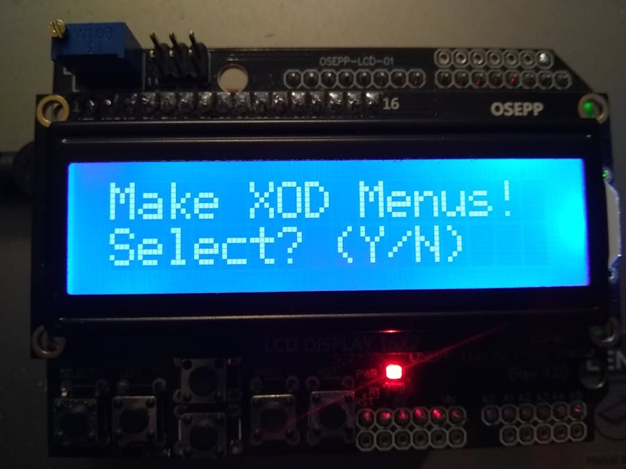
Code-Free LCD Menu Generation Using XOD
DFRobot
Feb 12 2019 260898
Things used in this project
Hardware components
Arduino UNO & Genuino UNO
DFRobot Arduino LCD/Keypad Shield
Software apps and online services
XOD Environment
Story
The processors that power the Arduino development boards aren't your granddad's microcontrollers - they've got serious processing power and can be used to monitor and control many types of physical hardware and sensors simultaneously. The XOD graphical programming IDE for Arduino can simplify the task of rapid-prototyping hardware designs, but as a system grows in complexity there's the issue of user control and information management - how to arrange information about the process being controlled for display and let the user control it in a logical manner. Dedicated buttons and switches work for simple projects but one soon runs out logical ways to arrange them (or places to put them on an enclosure.) Many designs use a display of some type to give this kind of feedback, even a microwave oven usually has a small screen that allows editing settings and entering cook times, and while too much "menu diving" to access obscure settings can compromise user experience, menu-driven interfaces are a fact of life for projects of all kinds.
Software frameworks for developing menu-based interfaces in C or C++ for microcontrollers often have a steep learning curve and can be difficult to make rapid design changes in, as often everything interacts with everything else. The goal of this project was to use the XOD graphical programming environment to provide the ability to rapidly prototype menu-driven interfaces for Arduino-compatible microcontroller projects using a drag-and-drop/WYSIWYG style of interface. The output and input parameters of the generated menu structure are modular and generic and should be able to be used with a wide variety of input sources (switches, buttons, encoders) and produces a sequence of plain text outputs which can be fed to a wide variety of XOD-supported display types, including multi-line text LCD modules as used in this example.
If you aren't familiar with the XOD environment this project uses, please check out the tutorials for that project first at xod.io.
A screenshot of a simple motivational example sketch follows. We'll go through this XOD patch diagram piece by piece to show how everything fits together.

The Menu Controller interface section
At the right of the patch editing screen in XOD are four nodes connected up in a descending fashion. From top to bottom there's first an analog input-type node, which is selected to be connected to one the Arduino's analog input ports. In my tests I've been using an Arduino Uno with an ATMega328 8 bit processor, with a 16x2 LCD/keypad shield connected on top of it. The keypad on the shield is connected via the shield pins to the Arduino's "A0" analog input, and the hardware generates voltages of differing levels to signal to the Arduino which buttons on the pad are depressed.
Other than the "reset" button on the keypad which doesn't interface to the Arduino sketch directly, this type of display shield provides four directional buttons - up, down, left, and right, a "select" button. The second node down fed by the analog input node contains code which reads the differing voltage levels and outputs pulse-type triggers depending on which button is pressed. A "timeout" input is provided so an XOD developer can adjust the debounce timeout of the LCD shield keypad to avoid false triggering, adjusted to a particular application's button or switch type.
The third node down is a menu controller-type node, which contains code to accept pulse-type triggers from the control panel and handle the logic of the user navigating through the menu tree and making selections that generate state updates of the menu tree.
As currently implemented it accepts a single Number-type input which can be any parameter the user can change from an external control, say a potentiometer or dial on a control panel which represents some parameter that can be changed. When a given leaf-type menu is selected by the menu-controller receiving a pulse to its "Invoke" input, over in the menu tree to the left the node of the screen the user is currently looking at will output a pulse on its own output, and also send out a parameter change. There are also two String inputs which can be used to generate a splash screen on the display when the Arduino powers up.
Following that node is a stock 16x2 LCD controller module from the XOD environment standard library, but any type of display that a module is available for can be used to display the output text here.
The Menu Tree section
At the top of the sketch screenshot is a tree-like structure which, when compiled and the final output "root" of the tree is routed to the menu-controller input that accepts it, will automatically generate a navigable menu just as pictured in the graphical designer. Currently implemented are three types of menu tree nodes, a "leaf"-type menu - a final sub menu, with no orange-colored input ports - this represents some action or parameter the user can control, a "branch"-type menu with both an input and output, where the user can select among several child sub-menus, and a "concat"-type menu where sub-menus are grouped together and fed into the input of a branch-type menu, to make a group of options. It should hopefully be somewhat self-explanatory from the diagram how to wire up this set of nodes.
Selecting "invoke" when a "branch"-type menu is displayed descends into its associated sub menu group, rather than generating an output as a leaf-type menu does. Sub-sub menus, sub-sub-sub menus, etc. are possible! Complex structures can be implemented, limited primarily by the available RAM and Flash memory resources of a particular Arduino model's processor.
Output section
In this example the output section is where the leaf-type menus interface to external hardware via the Arduino's output pins. Each leaf-type menu has a Pulse-type output which connects to a respective flip-flop via a bus, to toggle its associated digital output pin on and off. This kind of arrangement could be used to control external relays or LED, but Pulse outputs are very general, and the output pulse generated when selecting "Invoke" when accessing a leaf-type menu's screen could be used to do lots of tasks, such as updating an internal XOD buffer-type node where parameter data from the menu controller's parameter-type input port is retained for future use.
Current known issues
This set of nodes has been tested and should work OK with the Arduino Uno as-is, but a few issues remain that weren't resolved by this project's deadline. Currently there must be a branch-type menu in the tree somewhere for a sketch to compile, though most projects would probably want to have at least one. The "top" menu input to the menu-controller, intended to return all the way back to the title screen of the interface, isn't currently implemented but should be an easy feature for the next revision.
Four-line displays are supported by the menu controller node but the leaf-type menu interface with four lines of text input hasn't been written, yet. A good amount of effort has been put into reducing the memory overhead of this utility but the way the XOD transpiler currently stores constant strings isn't optimal for very low RAM overhead, and menu-based interfaces tend to have a lot of text. For this project a work-around was developed and a set of flash-string type nodes added in the patch to ensure longer strings did not consume precious program RAM.
Hopefully this will be addressed in an update of the XOD environment, but the work-around does OK for now.
Using the flash-string type nodes isn't too painful but does require duplicating the patch and code for each new string stored in program memory, and clicking into the C++ code contained within the node itself to edit the output string:

The "ID" input of leaf and branch nodes doesn't have a function, yet. The thought is it would be good for each set of sub-menus to have associated ID numbers arranged in order so the user can keep track of their position in a set of displays but it will require some more thought on how to code this in C++ to happen automatically.
Continuing work
Further bug testing and testing on other Arduino devices besides AVR/ATmega devices such as ARM should be done. The current set of menu-node types is somewhat limiting there should be more variety of input and output. Continuing work on reducing the RAM overhead, perhaps by using more compile-time metaprogramming and storing as much data in Flash memory rather than interconnecting/concatenating the tree components at run-time.
More project Information here.
Recent Blogs

FireBeetle 2 ESP32-C5 IoT Development Board Review: Dual-Band Wi-Fi 6 and Solar Charging
Explore the new FireBeetle 2 ESP32-C5, a powerful IoT development board featuring dual-band 2.4/5GHz Wi-Fi 6, multi-protocol support (BLE, Zigbee, Thread), and integrated solar charging. See how it outperforms the ESP32-C6 for advanced, low-power projects.
REVIEWS ESP32 Jul 15 2025

DFRobot at FAB25 Czechia 2025: Unihiker K10 AIoT Workshop & Free Trials | Brno Event
DFRobot showcases its revolutionary Unihiker K10 AIoT board at FAB25 Czechia with interactive workshops, free device trials, and exclusive maker gifts for attendees.
NEWS Jun 11 2025

FireBeetle V1 vs V2 (ESP32/ESP8266/Arduino) Development Board Selection Guide
The Selection guide comparing the FireBeetle (V1) and the FireBeetle 2 (V2) boards, particularly ESP32/ ESP8266 / Arduino versions.
SELECTION GUIDE ESP32ESP8266 Jun 08 2025