PROJECTS Arduino 
1.1 Making this smart fan requires the following materials:


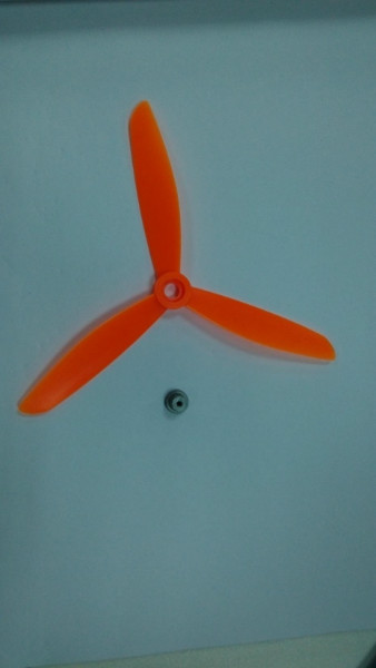
2.8 Fan blade couplings

After the system has been assembled as a whole requires a program to run it, first determine the function:

How to Build A Smart Cooling Fan with Arduino
DFRobot
Jul 02 2015 263796

It's getting hotter and hotter everyday. Electric fans are best if you don't have A/C with you. Traditionally, fans are generally controlled by remote control or by hand: when we feel hot or muggy, we move to turn on the fan. But a different, better option exists: when you sit in front of a fan, the fan automatically senses your presence and turns on. This would remove the need for manually controlled and remote controlled fans.
As the time passing by, repeated use of energy more and more attention by scientists, so the spirit of saving energy to make this kind of intelligent in terms of fan, it can detect whether someone, and then select open or closed fan, makes the fan became more intellectual and save energy.
Energy consumption is a big waste, both to consumers and scientists. In this present day and age, the public has moved towards eco-friendly products that both conserve energy and costs. A smart fan satisfies both of these conditions: the fan automatically turns on upon sensing your presence, meaning it doesn’t use more energy than necessary, making it cost and environmentally useful.
So, here is how to build a smart cooling fan using Arduino and IR sensor.
Parts List
- Rear case for fan blade 1 3D Print Model
- Front case for fan blade 1 3D Print Model
- Bracket 1 3D Print Model
- Rear case for speed adjustment knob 1 3D Print Model
- Front case for speed adjustment knob 1 3D Print Model
- Installing the base 1 3D Print Model
- Fan blade couplings 1 Ebay
- coupler 1 3D Print Model
- 9V 130 motor 1 Ebay
1.the Circuit
1.1 Making this smart fan requires the following materials:- Arduino UNO R3
- 2A Motor Shield for Arduino
- Sharp GP2Y0A21 Distance Sensor
- Analog Rotation Sensor V2
1.2 Circuit design of the fan’s design scheme is represented through the below flowchart:

1.3 Based on the ideas in the above flowchart, we can build the below electronic circuit diagram

2.the Mechanical
2.1 First build the electric circuit. Now, we need to build a frame to hold the hardware. To do this, we need to design a frame that holds the fan in place, such as in the picture below:

2.2 Rear case for fan blade: the middle section is used to fix the motor in place, before while the outer four holes are used to connect to the front case

2.3 Front case for fan blade: the middle section is used for fixing the distance sensor into place, while the outer four holes are used to connect to the rear case

2.4 Bracket: bused to support the bracket for the head of the fan; the bottom hole is used for fixing a nut into place

2.5 Rear case for speed adjustment knob: this case is used along with the front case to protect the speed adjustment knob


2.6 Front case for speed adjustment knob: this case is paired with the rear case; the two combined together resemble the upper-right photo.

2.7 Installing the base: the base is used to support the entire fan and also fix the microcontroller into place.

2.8 Fan blade couplings
Fan blades 6 inch, for good blades fixed on the 2mm axis, need to make an additional coupling, as shown in the figure.
Fan blades & axles: the fan blades measure 6’ inches each. In order for them to be stable, they should be installed on 2 mm axles. (the axles would need to be manufactured separately). The resulting product should resemble the above picture.
2.9 Rendered image of proposed Smart Fan

3.the Software
After the system has been assembled as a whole requires a program to run it, first determine the function:
After the software system has been installed, a program is needed to operate the fan. We first need to determine the following functions:
3.1. The fan works properly, while also being able to adjust the size of the fan.
3.2. When people are in the radius of the fan, the fan automatically turns on; when people leave the fan’s radius, the fan automatically turns off.
3.3 Based on the description of the above functions, we can complete a flow-chart illustrating the working principles of this software program, as seen below:

According to the flow chart shown in above, we set the following code:
int E1 = 5;//Define fan pin
int F1 = 4;//Define fan speed output

void fandriver(int a,int i)   //Define fan function is used to start the fan and controls the speed of rotation;
{
  analogWrite (E1,a);
  digitalWrite(F1,i);
}
uint16_t get_gp2d12 (uint16_t value) //Range operation functions for handling range sensor data sent back;
{
        if (value < 30)
                value = 30;
        return ((67870.0 / (value - 3.0)) - 40.0);}
void setup() {
    for(int i=4;i<=5;i++) pinMode(i, OUTPUT);
    pinMode(A1,INPUT);
    pinMode(A0,INPUT);
}

void loop() {
    uint16_t value1 = analogRead (A0);    //Receive information from the data;
    uint16_t range = get_gp2d12 (value1);    //Processing received data;
    if(range<1000)
    {
      Motor_speed=map(analogRead(A1),0,1024,0,256);  //Match speed to motor speed;
      if(Motor_speed<30)Motor_speed=0;   //Threshold settings for a filter fan not turn speed;
      fandriver(Motor_speed,1);     //Starting Fan;

    }
    else
      fandriver(0,0);         //Stopping Fan;
}
Enjoy!


