Arduino/Genuino 101 Starter Kit Tutorial - Lesson 10: Light Regulator
This is the 10th tutorial for the Arduino/Genuino 101 Starter Kit.
The light regulator is a device with which you can control brightness of the light. In this session, we’ll show you how to control brightness of the light with an analog rotation sensor. The light will turn from dark to bright or the other way along with the change of the rotation angle. The bigger the rotation angle is, the brighter the LED light is, and vice versa. You can make a light regulator for your own light at home.
The rotation sensor can also be used to control the rotation angle of a steering gear. you can also use it to control the rotational speed of a DC motor. You can find many uses for the rotation sensor.
COMPONMENT LIST:
1× Gravity:Digital Piranha LED Module-Red
1× Gravity: Analog Rotation Sensor V1
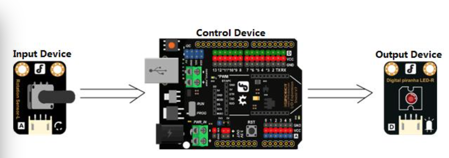
HARDWARE CONNECTIONS
Attach the potentiometer to analog pin 0 Attach the Digital piranha LED-R to analog pin 9
See the diagram below for reference:

Be sure that your power, ground and signal connections are correct or you risk damaging your components.
When you have connected the components and checked your connections, plug the 101 in to your PC with the USB cable so you can upload a program.
CODE INPUT
Sample Code 6-1:
// Item Six—Light –regulator
int potPin = 0; // Analog Rotation Sensor shall be attached to analog pin 0 int ledPin = 9; // LED shall be attached to digital pin 9
void setup() {
pinMode(ledPin, OUTPUT);
}
void loop() {
int sensorValue = analogRead(potPin); // collect value at analog pin 0
// A value between 0 and 1023 to mapped to a value between 0 and 255
int outputValue = map(sensorValue, 0, 1023, 0, 255);
analogWrite(ledPin, outputValue); // write corresponding value for LED
delay(2);
}
Use this sample code to implement the behavior we want.
You can copy and paste it in to the Arduino IDE, but if you want to develop you skills we recommend typing it out.
When you have finished, click “Verify” to check the code for syntax errors. If the code verifies successfully, you can upload it to your 101.
Turn the shaft of the potentiometer slowly. The LED’s brightness should change as you turn it.
HARDWARE ANALYSIS (ANALOG INPUT-ANALOG OUTPUT)
In the last session we learned how to achieve analog output with a digital pin using PWM. In this session, we are going to control analog output using analog input.
In this device, the rotation sensor is the input device. The LED is the output device. Both the input and the output device use analog values.
CODE REVIEW
We have used the “map” function. The map function is used to map a value within a range to one within another range. Let’s examine it a little closer:
The function’s syntax is as follows:
map(value, fromLow, fromHigh, toLow, toHigh)
The function maps a value between "fromLow” and “fromHigh” to one between “toLow” and “toHigh”.
Meanings of parameters included in the map function:
- value: value needs to be mapped from
- Low: lower limit of the current range from
- High: upper limit of the current range to
- Low: lower limit of the target range toHigh: upper limit of the target range
One advantage of map function is that the lower limit of both ranges can be a number bigger than their upper limits:
y = map(x, 1, 50, 50, 1);
The value included in the map function can also be a negative number:
y = map(x, 1, 50, 50, -100);
Let’s reexamine the code:
int outputValue = map(sensorValue, 0, 1023, 0, 255);
The above code is used to map a value (0~1023) read from the analog pin to one used in the PMW pin (0~255).


This article will explore how to install and run Qwen2.5 on a Raspberry Pi 5 using the Ollama runtime framework.
REVIEWS Raspberry Pi
In this article, we will delve into the process of installing and running the SLM(small language model) Gemma2 on the Single Board Computer (SBC) Raspberry Pi 5 using the Ollama runtime framework.
REVIEWS Raspberry Pi
In this write-up, we delve into the process of installing and executing phi3.5-3.8b on a Raspberry Pi 5, leveraging the Ollama runtime framework.
REVIEWS Raspberry Pi