PROJECTS LattePanda

Teleroomba

DFRobot Mar 01 2018 736

This project is created by Rubin Huang

Teleroomba

I hacked a Roomba vacuum and combined with Lattepanda to become a telepresence robot.
See the full 40 seconds Teleroomba introduction video on Youtube:


1. A concept sketch of a 360 telepresence robot.
Buying a telepresence robot is usually pretty expensive, and all you can do is drive a video chat on a moving platform.
 
I believe that an ideal telepresence experience should be much more immersive! Why can't we have a 360° view like real-life and use some of our body's actual gestures. But more than that, to be able share music videos or even clean rooms! It is going to be so much fun.
 
I decided to make my own unique model!


2. An inexpensive way to build a robot? Hack a Roomba!
What will be an affordable platform for me to build the robot upon?
I suddenly saw my cat is riding my roommates Roomba! That's it!
 
I find the iRobot Create: A hackable vacuum robot!
This robot allows you to hack it's serial port and access all it's function.
 
You can find more information here on iRobot's site.
http://store.irobot.com/default/create-programmable/
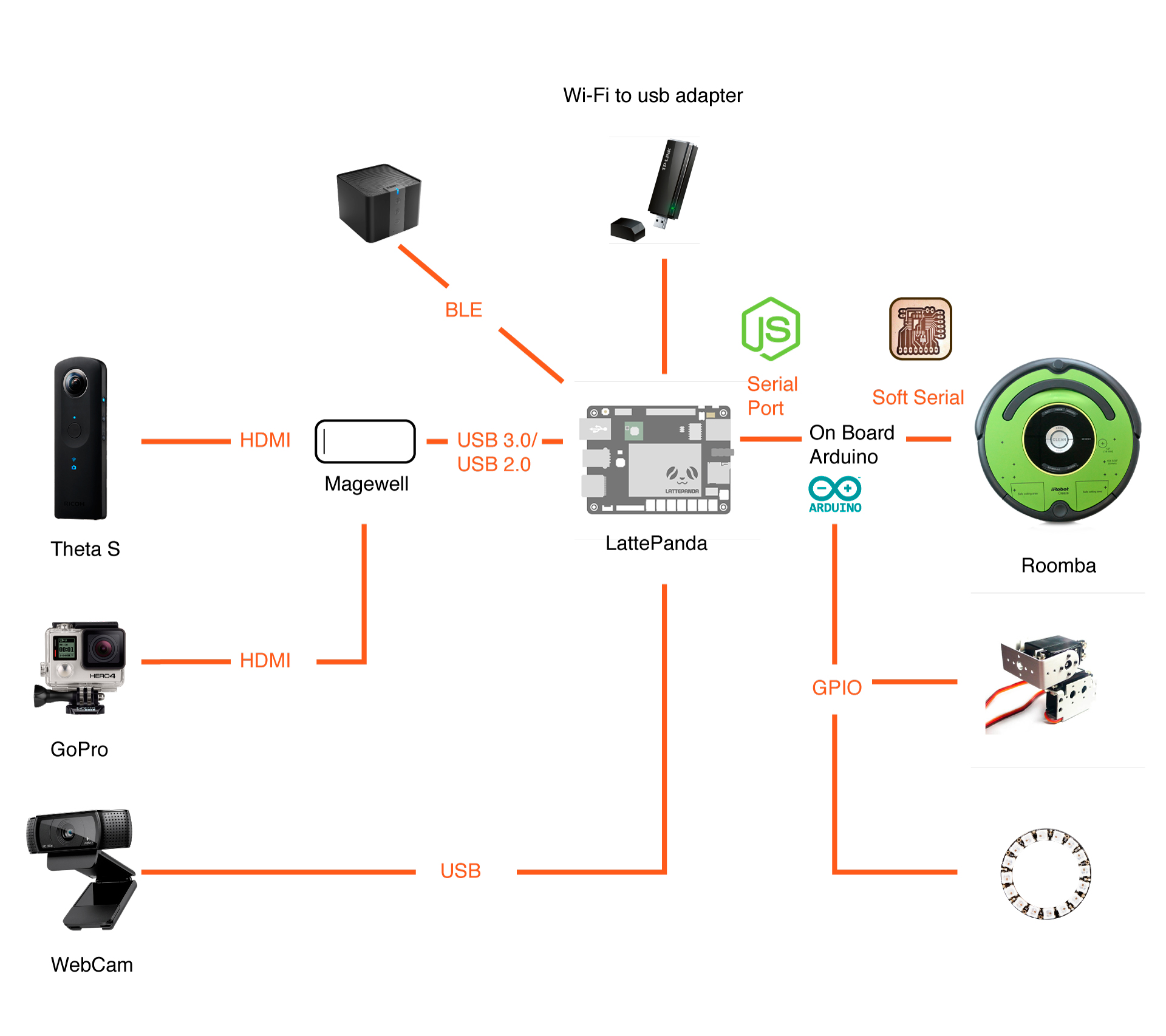

 
3. Figuring out the hardware.
It was important to find the right hardware for the right experience:
Strong connectivity, audio playback, displaying images and animations, and robotic parts for the movement.
 
(Above is an early map, some things have changed since then.)
 
4. What operating system?
I need to find a solution to integrate everything together as much as possible.
A mini computer solution called “Lattepanda”, which is a small but powerful mini computer that can run Linux or Windows 10. (I first looked into Raspberry PI, it turns out that I need more power to handle the streaming technology like WebRTC.)
 
I tried to run linux Mint on it in the beginning but soon I go it back to Windows, the reason is simple: Windows just works good with all kinds of hardwares without me finding their drivers one by one.(It is much more complex to install hardware drivers under linux, like display, touch screen, wifi adapters, bluetooth, etc. ...)
 
You can find more about lattepanda here:
https://www.dfrobot.com/product-1498.html 

5. Bringing a roomba to human size.
Since the Roomba is too short to hang a display on it, I need to design a support to make the display goes higher enough for a interpersonal communication, also I need some kind of frame to attach a camera, a display and my “Lattepanda” mini computer to the Roomba base.
 
I have a background in illustration so i enjoyed drawing sketches of my design.
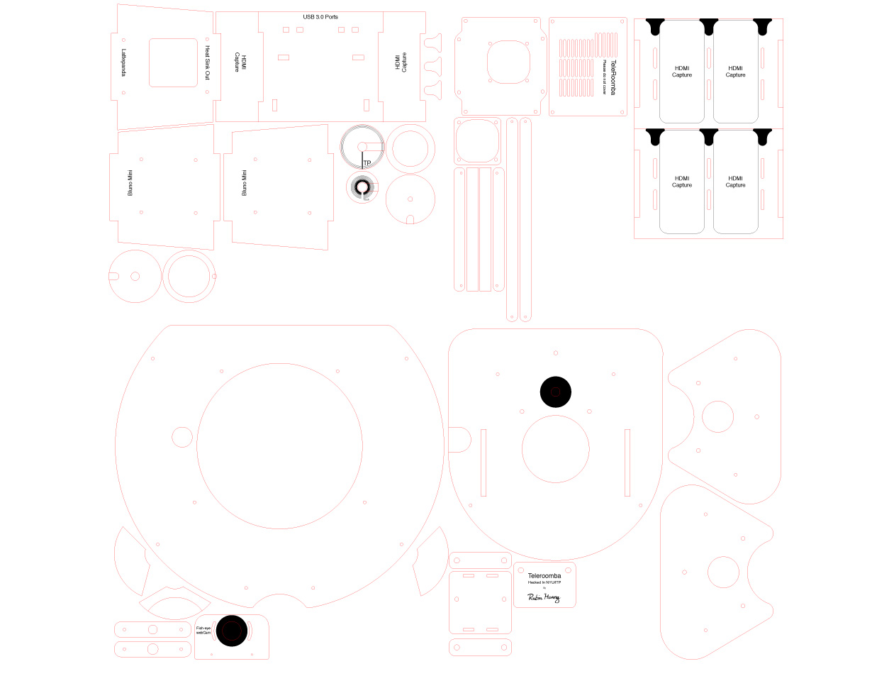

 
6. Fabrication with lasers.
I ended up with an "acrylic + monopod" structure. It allows me to still adjust the extendable monopod to the height of the robot after assembly.
 
Then I turned my designs into vector files for fabrication with acrylic and laser cutters. I choose the clear acrylic to be the material since I really like the design that exposes the detail of technology.
The cutting goes smoothly and the next step is assembly.


7. Overheating? Cool it down.
Streaming video is tough work, it will heat up the mini computer in just a few minutes.I installed heatsinks on the circuit and used a mini fan to blow the hot air away.
The fan is installed to an acrylic frame and then attached to the backside of the Mini computer where the processors are located.


8. Installing the mini computer unit to the main frame.
You can see the cooling system go through the frame and protecting the fast spinning fans inside, while the antenna is exposed to the outside.


9. Managing the cable mess with a customized PCB Adaptor.
As I connect more and more stuff to the Roomba, things are getting messy, time to clean them up.
To connect the GPIOs on “Lattepanda” to the Roomba’s serial port, I made a simple PCB(Printed Circuit Board) as a adapter, later on I also added ports for driving LED indicators and servo motors.
 
Above is a short video which shows how the PCB evolved over time and how all the components connect to the PCB at once.
 
10. Making the Mini DIN serial cable.
The serial port on the Roomba is a Mini DIN female connector, I ordered the male connector and soldered a jumper wire to each pin and made my customized serial cable, the other side plugs into the PCB I have made in the previous step.
 
11. Installing and assembling the rest: Camera, speaker, display.
Before I enable the 360° video capture of the Teleroomba, I also added a controllable 2D front camera.
 
A 2D camera delivers a better video quality and orientation sense while driving,  also by using a USB web camera, i will never have to worry about running out of the camera's battery since it is always plugged into power. I can switch in between two cameras( front 2D camera and 360° camera ) on what I need.
 
The speaker is mounted opposite to the 2D camera. It connects to the mini computer via bluetooth.
 
The mini touch screen on the Teleroomba has Windows touch support and made the interface easier to interact with.
The Display sits on top of a tablet clamp and fixed to the monopod with a GoPro accessory.
 
Then a NeoPixel ring indicator and a thetaS camera is sit on the top of the robot.
 
12. Building the controlling software. 
It is hard to describe what code exactly I put into this thing, but at least I can give you an overview of it here!
 
The image above is a overview map of the software.
There are basically 3 kinds of code to keep the robot running:
 
[Controller side]
Connecting with HID, controllers such as joystick and headset (Node.js)
 
[Robot side]
Running the serial bridge, reading the file system, controlling servo motors and LED indicator.(Node.js/Bash/C/Arduino)
 
[Web service]Serving web based interfaces, establishing WebRTC and tcp sockets. (Front-end JavaScript/Node.js)
 
To establish a video and audio call to the robot, I used Google’s WebRTC, which combines a low latency media stream with a data channel. WebRTC allows me to send real-time data along with the video stream. So on the software perspective, it is a web app and it runs directly in Google Chrome(both controller side and the robot side).
 
Learn more about WebRTC: https://webrtc.org/
 
13. Controlling the robot
Method 1: Game Joystick
 
This old joystick is the "Logitech EX3D" (I found it on the “Junk Shelf” at school).
 
You can still find that antique on amazon:
https://www.amazon.com/Logitech-Extreme-Joystick-Certified-Refurbished/dp/B00TQ8LNNA/
 
I used a library called Node-Logitech-Extreme-3D-Pro which is a node.js based serial communication library that was conveniently written especially for this old Logitech joystick (!!!), so I was able to get data from the joystick and send these values to my web app with web sockets pretty easily.
 
You can find the code on GitHub:
https://github.com/botonchou/node-Logitech-Extreme-3D-Pro
 
With that joystick, I can control the movement of the robot, adjust it’s moving speed and also the pitch and pan of the front 2D camera. I also made a UI system for easier and precise control. Here is a small demo of how it visualizes the position of the joystick for the user.
 
By using the joystick I can have very smooth control of the robot, it has nice easing when accelerating or slowing down.
You can see an image of myself on the robot display, with the speaker on the back, people can hear me talk.
 
The short video above shows the smaller joystick on the top can control the view of the front camera when you're not in VR mode.
 
method 2: Keyboard and trackpad
 
I also programmed a virtual joystick for when i don't have a joystick. It works really well. I can easily send commands like drive straight, make a turn, go backwards etc.
 
There are sliders on the interface to control the front camera, I can drag it to adjust the viewing direction.
 
In VR mode, to control the front camera I used the headset's accelerometer and gyro system to track my head movement and mapped it to the tilt and pan of the 2D camera.
 
VR mode in action!
I was very surprised that the latency was almost unnoticeable, the camera works seamlessly.
When I switch to this mode, the LCD display shows a cartoon character of the robot instead of my face, his eyes on display sync with the viewer's viewing direction.
 
I can still drive the robot around with the joystick or keyboard.
 
14. Going for the 360° View
The most exciting feature for me is the ability to drive with a 360° view.
The Ricoh's thetaS camera can live stream from both it’s USB Mini port and the HDMI port, however the raw image I received directly from the camera is a "2 semi-sphere projection" image, the first thing I need to do is restore the 360° image.
Luckily, I found a piece of code from the following blog post.
https://bl.ocks.org/mechamogera/5635338a1075baadba0b/
 
This code maps the projection onto two semi-spheres with the three.js javascript library, which i hacked to add manual adjustment functions for improving the stitch. https://rubinhuang9239.github.io/Spherical-Merge/
 
Further explanation of the 360° image projection is here.
http://qiita . com/mechamogera/items/b6eb59912748bbbd7e5d/
 
The video above shows how the 360° video stitch system work.
 
Finally !!!
A video is more than thousand words!
 
I got the real-time 360° feed and I can explore all angles while I am driving the bot, and switch into the crystal ball view at anytime. This 360° view also works on mobile devices, which means you can have that experience with a google cardboard like headset, very immersive.
 
This is a 360° video I recorded from the Teleroomba. (Recorded at NYU ITP) Don't forget to drag and move on your player to see the recording in 360° view.
https://youtu.be/tDMo28dYrG8
 
16. Other features 
UI: focusing on driving.
 
I categorized the robot’s function and designed this navigable sidebar, so I can keeping the maximum view of the image from the robot’s camera.
 
Debugging tools
This is the developer console interface with color coding to help me address problems and bugs faster.
 
LED moving direction indicator
 
It tells you where it is heading.
 
There is a NeoPixel LED indicator for visualizing which direction Teleroomba is heading, rotating lights means the Teleroomba is rotating in place.
 
The bill of materials
Here is a nearly comprehensive list of things I used to build the robot. The overall expense is around $700, it is cheaper than most of telepresence robot I can find on the market. Except for what I've I built on my own, I ordered most components listed above from amazon. Plus I had a lot of fun making it.  :)
 
Here is a Google Doc containing all the links to find those materials/components to the best of my memory.
https://docs.google.com/document/d/1JzjGCMMSeq3ltRw8iQZK2rDNfjw0zbAjN0zkChpK6rI
 
Wrap-up and Thanks
Well that's all about this robot I have worked on for the last 6 months, so I wrote this post and I hope you liked it.
 
In the end I want to thank professors and friends at NYU ITP who helped me along the way.
Especially I would like to thank iRobot and DFRobot who provide such good product for me to develop my project upon.
 
To see more of my projects, or if you want to connect with me, please visit:
http://rubinhuang.com