Mongoose OS on ESPer/Bare ESP32
So recently I had been reading about a lot of IoTs(Internet of Things) and trust me, I just couldn't wait to test one of these wonderful devices, with the ability to connect to the internet, myself and get my hands on work. Luckily the opportunity arose, thanks to DFRobot, and I was provided with ESP32, a powerful, hybrid and awesome module.
To begin with, I purposely asked the DFRobot team to send me the ESP32 module rather than the development board because I couldn't let the thrill of skilful get past my hands. And hence, here we are, making ourselves our own development board for ESP32.
My main aims for this board were as follows:
-The development board must be breadboard-friendly.
-It must have EN(Reset) and FLASH tactile switches.
-One-sided PCB layout.
I chose one sided layout because not everyone has access to double sided PCBs, me being one of those people.
-No in-built UART communication circuitry.
This was quite a trade-off because the one sided layout could only give enough space. Therefore we'll be using USB to TTL Converters externally to flash it.
-Like Arduino, I wanted to have an inbuilt LED for reducing recurring LED wirings.
-Compact, yet easy to solder and make.
-A detailed silkscreen.
-Use the GND solder pad in ESP32 for better heat loss.
Fortunately, I was able to fulfil all the above-mentioned aims after designing various PCB layouts. That being said, let's proceed with the instructable.
Step1: Gather Around some stuff
Making this development board requires only the basic articles if you exclude the SMD resistors and of course, our very own ESP32.
Primary Requirements:
1.ESP32 Module
2.Copper Clad Board : You must have at least 4cm*5cm block of copper board.
3.SMD Resistors:
10k - 2 pieces
1k - 1 piece
4.3mm LED (Any colour)
5.Male Headers - 38 pins
6.Tactile Switch - 2 pieces
Secondary Requirements:
1.Soldering Iron: I'm using the soldering kit provided by DFRobot. It was very handy in making this instructable. For fine soldering, I had to use an additional fine soldering horseshoe tip.
2.PCB Drill: Don't have one? Why not try making one yourself! Here's how
3.Ferric Chloride: This will be used for etching purposes.
4.Sanding Paper - Zero Grade
5.Clothes Iron
6.Any PCB Cutting Tool
7.Double-Sided Tape
8.A Permanent Marker
9.Scissors
10.Acetone
I wanted to do things cleanly, if you don't then you may simply skip this.
I have attached the board files of eagle for giving you modification freedom.
That's all for the requirements, if you have all the above-mentioned stuff, proceed further.
Step2 : Making the PCB
I'll be making the PCB using the remedial Toner Transfer method. Print out the attached PDF on the requirements step on a glossy paper, the one that feels good to touch. Once you have a crisp printout of the layout on a (white)glossy paper, then there's no more stopping you, therefore begin with the PCB making process.
I'm stressing on the glossy paper being white because later on we'll be cutting off the silkscreen from it. I don't have a white glossy paper, therefore I took two printouts of the same layout.
The PCB manufacturing process has been covered in detail in another one of my Instructables.
Making PCBs at Home
I'm attaching the pictures of how this PCB was made, above.
For drilling, use 1mm drill bits or below.
Step3: Soldering the Components
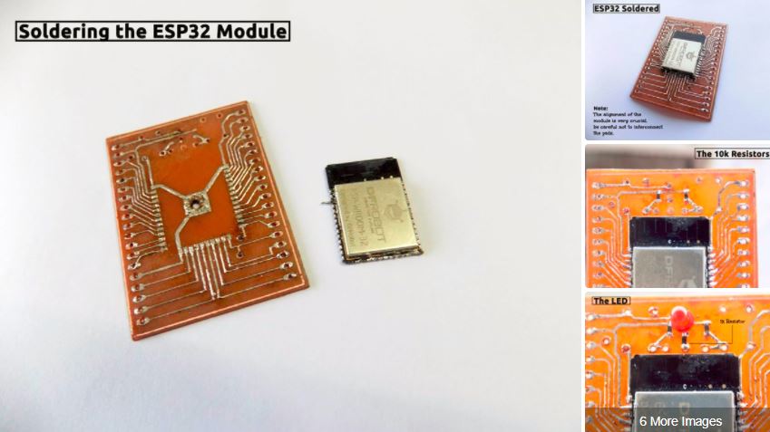
Begin by soldering the ESP32 onto the PCB. Certain things to be kept in mind while soldering this challenging, yet fun module are stated below.
-Alignment of the module with the solder pads, the first step, is the most crucial part of the whole thing. Mess this up and you'll suffer non-working GPIOs and maybe even a non-working module!
-Use pointed soldering tips to prevent the dismantling of traces or solder pads due to overheating.
-While soldering the ESP32 module, solder the diagonal pads first so that the chip doesn't mess up its alignment.
-Solder the GND pad of ESP32 by heating the solder in that pad through the hole drilled in the centre. This will heat the solder on the GND pad of ESP32 and merge it with the GND pad on the PCB.
Once you're done with that, solder all the components one by one in their respective places by referring to the above pictures. The correct order for soldering the components is:
1.ESP32
2.SMD Resistors
3.Tactile Switches
4.LED
5.Jumpers
6.Male Headers
The jumpers are three in number. In the screenshot of eagle layout posted above, the blue wires represent the jumpers. Here, enamelled wires have been used as jumpers.
While soldering the headers, placing ESPer on breadboards perfectly aligns the headers.
After soldering all the components carefully and correctly, clean the whole PCB by using an old toothbrush(also useless). This removes all the excess flux.
Step 4: Pasting the Silkscreen
Now our ESPer is completely functional but it still lacks something, and that is a silkscreen. Adding this silkscreen will rid us of continuous referring to pinouts. To stick it to the board, I'll be using double-sided tape. The silkscreen can be attained through the layout printed earlier.
If you have doubts regarding your work or wiring, this is the time for checking it. Because after following the later steps, you won't be able to modify your board in any way. Proceed with caution.
Now proceed with the silkscreen by doing the following:
-Cover the entire ESPer board with double sided tape bits, except the ESP32 part.
-Then align the silkscreen and paste it into the double-sided tape carefully.
-After that, remove the amount of paper above ESP32 to expose it, and fill the left empty spaces using hot glue.
That's all for this step.
Step5: Congratulations!
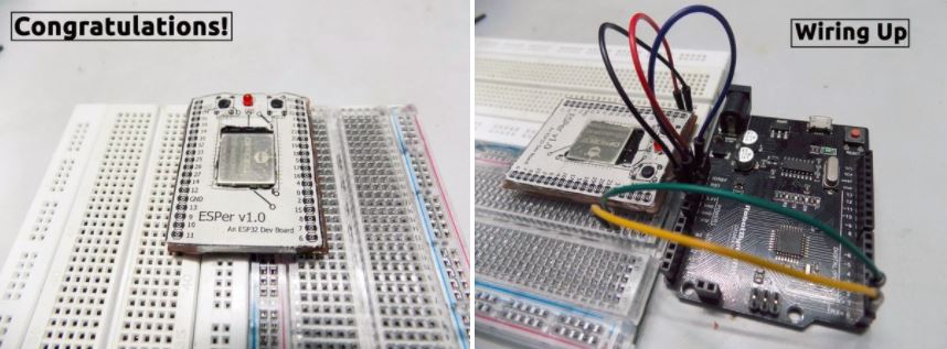
Did all the previous steps? If yes, then congratulations because that's all for this instructable.
Now you can use your ESP32 module just like any other development board just by wiring it up with any USB to TTL Converter(even your Arduino). The wiring is simple, just power ESPer using a 3.3V power supply and make the UART connections(Rx, Tx). When using Arduino, ground the RESET pin to use it as a TTL Converter. I'll be covering up more about ESP32 using this development board in the upcoming Instructables.
I have created a GitHub repository for storing the files for this instructable.
I've embedded a video which shows the ESP32 handling the Blink code which I had flashed through Mongoose OS.
I've removed my silkscreen because I had to do further improvements for other projects.
You can do the same by following this Instructable which covers how to use ESP32 as Arduino. If you want to use Mongoose OS instead, visit this post of mine: Mongoose OS on ESPer
Meanwhile, I'd like to thank DFRobot.com for sending me awesome stuff like the ESP32 and giving me the opportunity to tinker with them. Even words aren't enough to express my gratitude.
That's it for this instructable. If you have any doubt, feel free to comment. Don't forget tofollow me if you liked this instructable. Please support me by reopening the shortened links twice or thrice. You can also support me on Patreon.
Keep Tinkering!


