TUTORIALS ESP32 The objective of this ESP32 Arduino tutorial is to explain how to get measurements from the ESP32 internal Hall sensor. The tests of this tutorial were performed using a DFRobot’s ESP32 module device integrated in a ESP32 development board.
The tests of this tutorial were performed using a DFRobot’s ESP32 module device integrated in a ESP32 development board.
ESP32 Arduino tutorial: Internal Hall sensor measurements
DFRobot
Apr 25 2018 261360
The objective of this ESP32 Arduino tutorial is to explain how to get measurements from the ESP32 internal Hall sensor. The tests of this tutorial were performed using a DFRobot’s ESP32 module device integrated in a ESP32 development board.
Introduction
The objective of this ESP32 Arduino tutorial is to explain how to get measurements from the ESP32 internal Hall sensor, using the ESP32 Arduino core.
An Hall sensor is a device that, when under the effect of a magnetic field, outputs a proportional voltage [1]. This is one of the many sensores included in the ESP32 microcontroller [2].
We will first obtain the values when no magnetic field is nearby and then test the results when we approximate a magnet to the ESP32. The code shown here is based on this example from the Arduino core, which I encourage you to try.
The tests of this tutorial were performed using a DFRobot’s ESP32 module device integrated in a ESP32 development board.
The code
For this ESP32 tutorial, we will not need any library includes. Also, the setup function will be very simple and basically consists on opening a serial communication, so we can then send the Hall sensor measurements to a computer.
void setup() {
  Serial.begin(115200);
}
The rest of the code will be done in the main loop function. We will want to do a periodic measurement of the sensor values. But first, we declare an integer variable, to hold the result of each measurement.
int measurement = 0;
Then, to obtain the actual measurement, we simply call the hallRead function, which will return the value from the Hall sensor. Naturally, we will store the value in our previously declared variable.
measurement = hallRead();
After having the value, we will print it to the serial port, so we can then check the value using the Arduino IDE serial monitor.
Serial.print("Hall sensor measurement: ");
Serial.println(measurement);
Finally, we do a delay before getting to the next cycle of our measurement loop. To do so, we simply call Arduino’s delay function, passing as input the number of milliseconds to wait. In this example we will delay for 1 second, but you can play with other values.
delay(1000);
The full source code for this ESP32 tutorial can be seen bellow.
void setup() {
  Serial.begin(115200);
}

void loop() {

    int measurement = 0;

    measurement = hallRead();

    Serial.print("Hall sensor measurement: ");
    Serial.println(measurement);

    delay(1000);
}
Running the code
To test the code, just compile it and upload it to the board using the Arduino IDE. Then, open the serial monitor and set the baud rate to the same value defined in our setup function.
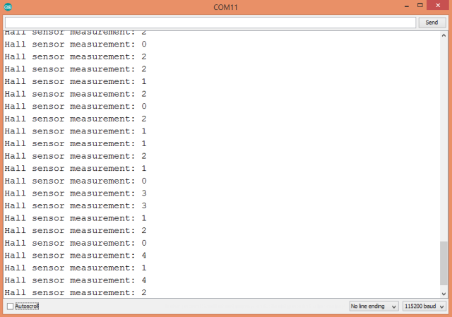
Without any magnetic field near the ESP32, you should get some measurements near 0, as can be seen bellow in figure 1.

Figure 1 – Hall sensor measurements without magnetic field near by.Then grab a magnet and put it near the ESP32 chip. Depending on the magnetic poll that is near, the values of the Hall sensor measurements should either increase or decrease, as shown in figure 2.


