PROJECTS Arduino Hardware components
Software apps and online services
Story
Greetings!
Outermost OLED pins are labeled with 1 and 20, so double check if each connection is assigned to proper pin
second button pins go to GND
for this build you will need this specific version:
https://github.com/adafruit/Adafruit_SSD1325_Libra...
Tamaguino Update with Huge OLED
DFRobot
Jun 03 2018 1900
Tamaguino was one of my first Arduino projects and my first game developed to run on a microcontroller.
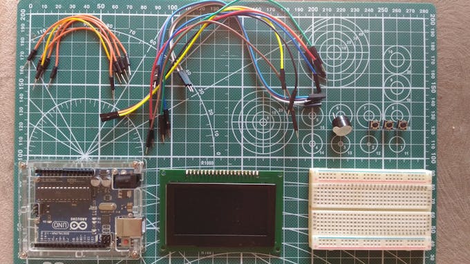
Hardware components
2.7" OLED 128x64 Display Module
Breadboard (generic)
Jumper wires (generic)
SparkFun Pushbutton switch 12mm
Arduino UNO & Genuino UNO
Software apps and online services
Arduino IDE
Story
Greetings!
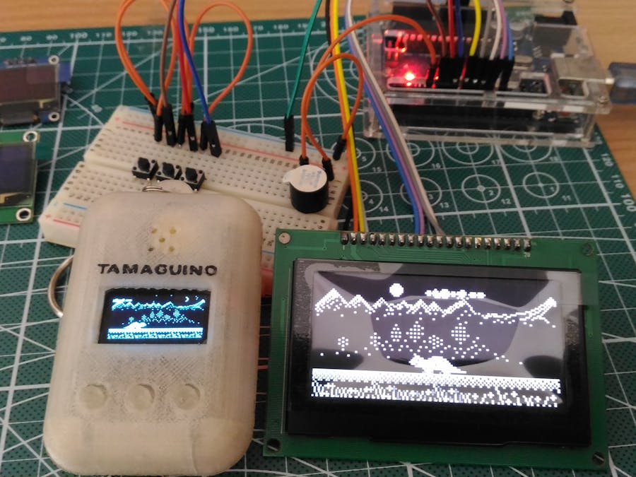
As you may already know, Tamaguino was one of my first Arduino projects and my first game developed to run on a microcontroller. It is a clone of Tamagotchi virtual pet, which were very popular in the 90's, and gaining popularity in last few years too!
First version of Tamaguino used well known 0.96" I2C OLED that is widely available and used by many electronics hobbyists.
Tamaguino has it's own website: https://alojzjakob.github.io/Tamaguino/.
There you can find detailed information and schematics, source code and related libraires, 3D printable cases and much more. It was ported to Arduboy too! ;)
Now that you know the brief history of Tamaguino, lets make it shine on this new big OLED!
Step 1: Parts Needed
Step 2: Wiring
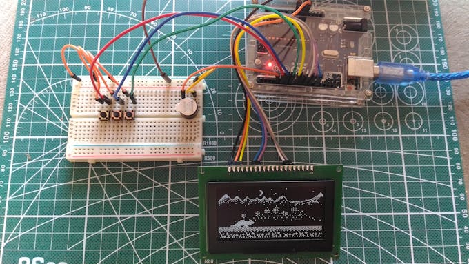
Outermost OLED pins are labeled with 1 and 20, so double check if each connection is assigned to proper pin
Please follow this guide for connections:
- OLED PIN 1 (GND) -> ARDUINO GND
- OLED PIN 2 (VCC) -> ARDUINO 5V (should work on 3v3 too)
- OLED PIN 4 (DC) -> ARDUINO PIN 8
- OLED PIN 7 (SCK) -> ARDUINO PIN 13
- OLED PIN 8 (MOSI) -> ARDUINO PIN 11
- OLED PIN 15 (CS) -> ARDUINO PIN 10
- OLED PIN 16 (RST) -> ARDUINO PIN 9
Buttons and buzzer / speaker:
- BUTTON 1 -> ARDUINO PIN 5
- BUTTON 2 -> ARDUINO PIN 6
- BUTTON 3 -> ARDUINO PIN 7
- BUZZER + -> ARDUINO PIN 4
- BUZZER - -> GND
second button pins go to GND
We dont need to use resistors for buttons, because corresponding Arduino pins used for button inputs are initialized with internal pull up resistors in the code.
Step 3: Uploading the Code
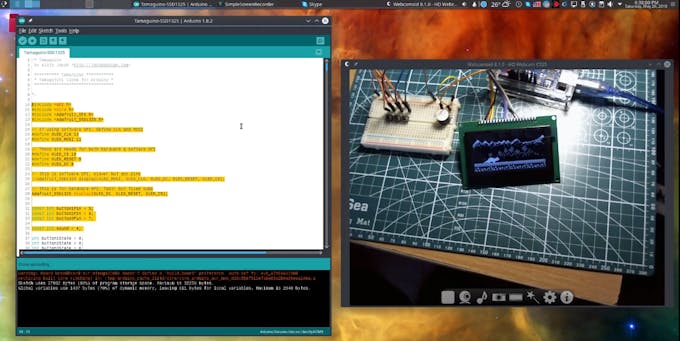
Source code can be found here:
https://github.com/alojzjakob/Tamaguino
for this build you will need this specific version:
https://github.com/alojzjakob/Tamaguino/tree/maste...
It is a modified version of initial code to be compatible with this screen.
If you were building Tamaguino before, please note that buttons and buzzer are mapped differently on this compared to SSD1306 (I2C) version. It had to be re-arranged so we can use SPI dedicated pins on Arduino.
You will also need this library from Adafruit for SSD1325:
https://github.com/adafruit/Adafruit_SSD1325_Libra...
Now that you have everything ready, load the code and library into Arduino IDE and upload to the board.
Step 4: Overview
In the video above you can follow me step-by step and build your own Tamaguino pet!
Recent Blogs

Run Qwen2.5 on Raspberry Pi 5 using Ollama
This article will explore how to install and run Qwen2.5 on a Raspberry Pi 5 using the Ollama runtime framework.
REVIEWS Raspberry Pi Dec 11 2024

Run Gemma2 on Raspberry Pi 5 using Ollama
In this article, we will delve into the process of installing and running the SLM(small language model) Gemma2 on the Single Board Computer (SBC) Raspberry Pi 5 using the Ollama runtime framework.
REVIEWS Raspberry Pi Dec 11 2024

Run phi3.5 on Raspberry Pi 5 using Ollama
In this write-up, we delve into the process of installing and executing phi3.5-3.8b on a Raspberry Pi 5, leveraging the Ollama runtime framework.
REVIEWS Raspberry Pi Dec 09 2024