
- Topic: mind+ local deployYou Reply:
You can check it out here.
- You Reply:
Is this the product? SKU:SEN0237
- Topic: Lattepanda Power SupplyYou Reply:
Here’s a 7-inch display: 7" 1024 x 600 IPS Display for LattePanda V1.
For power supply recommendations, check out this link:
https://docs.lattepanda.com/content/1st_edition/troubleshooting/#tested-power-accessories - You Reply:
When building a cluster with LattePanda Mu modules, it’s recommended to use one carrier board per module and connect them via Ethernet. For power, you can either use separate power adapters for each board or a single larger power supply to handle multiple boards. If choosing the latter, make sure it delivers enough voltage and current for all connected modules.
For deeper insights or questions, check out the LattePanda community forum: https://www.lattepanda.com/forum/.
- Topic: PCB: 8 metallized holesYou Reply:
After consulting the product team:
For the Gravity series (shown in your photo), the eight peripheral holes serve dual purposes:1.They're part of the signature design language.
2.The 8 holes around the copper can also make the copper coating more secure and not easy to fall off.
The Fermion series uses smaller central holes that physically can't accommodate this specific perforated reinforcement.
Think of it like architectural rivets vs. minimalistic pins - same functional principle, different execution to match each product's aesthetic!
Turns out our users have better eye for design details than my cat has for judging my life choices.
- Topic: PCB: 8 metallized holesYou Reply:
The number was chosen for symmetrical spacing and mechanical stability during installation - like having extra seatbelts in a racecar, even if you only technically need a few. Could it work with 4 or 6? Probably. But eight gives us a nice even distribution pattern that makes assembly processes smoother.
onsider it the industrial equivalent of pizza slices - 8 just feels more shareable than 6! 🍕
- You Reply:
I have found the schematic diagram, which you can refer to. Additionally, I think the issue might be with the SD circuit; you may want to check that.

- Topic: Are there any customer reviews or in-depth evaluations available for the ESP32-S3 AI Camera Module?You Reply:
Yes! A detailed customer review of the ESP32-S3 AI Camera Module is available here: YouTube Review
- You Reply:
UNIHIKER K10 is a controller that can also run some AI models.
Huskylens is an AI sensor that can run a wider variety of AI models, with faster recognition speed. It needs to be connected to a controller for use.
For more technical questions, please refer to: https://www.unihiker.com/wiki/K10/faq/
- You Reply:
1.The power supply of the digital pin is connected to SERVO_PWR, and SERVO_PWR supplies 5~12V. After the servo power input interface is powered, it can only power the D0 to D13 digital pin, but not the board. If the program burned in the board needs to run, the board must be connected to the other power supply. PWR_IN is connected to vin, PWR_IN power supply 6~12V. The power supply of the I2C interface on the Shield is 5V. Use the 5V/3.3V jumper caps to select the power supply for the digital and analog pins.
2. Pin header specifications
xh2.54mm
- You Reply:
Method for disabling the DFPlayer PRO beep:
The voice prompt is enabled by default when the module is delivered.
If it needs to be turned off, please set it in the AT instruction. The specific setting method and software used are as follows:
1.Download the SERIAL debugging software , you can directly use the software we provide(https://drive.google.com/file/d/1RgP0G4nEWa7h251SPwDiloATDb4KpNVc/view?usp=sharing), and in the main interface to change the language to English mode.
2.Connect Dfplayer Pro to your computer, open the Port column of Device Manager, and view your Dfplayer's COM number.
3.Open the serial debugging assistant, select the correct COM port, according to the following figure to set the correct baud rate;
4.Type AT in the input field and press Enter. You should see the window return "OK", indicating that the AT command has entered setup mode;
5.To turn off the hardware prompt tone, enter the command "AT+PROMPT=OFF" to turn off the prompt tone and save it after power failure.
For more AT instructions, see the Wiki interface description (https://wiki.dfrobot.com/DFPlayer_PRO_SKU_DFR0768).
- You Reply:
1. Check whether the code wiring is correct;
2. Whether the use method is correct, pay attention to use the strap to tie the module to the finger, and do not press the back of the sensor with your hand;
3. Check whether the plastic film on the sensor is in good condition, without plastic film SEN0203 can not work (it can be replaced by transparent tape)Note:It is recommended to fix the probe on the finger pulp when using the test

- You Reply:
Try installing an older Raspberry Pi system such as Debian 10 (Buster). Set system Resolution: 800*480.(The new version of the product has solved this problem.)
- You Reply:
Check to see if the correct extension is called, and enter the following URL on the search screen:
https://github.com/DFRobot/pxt-DFRobot_Environment_Science

- You Reply:
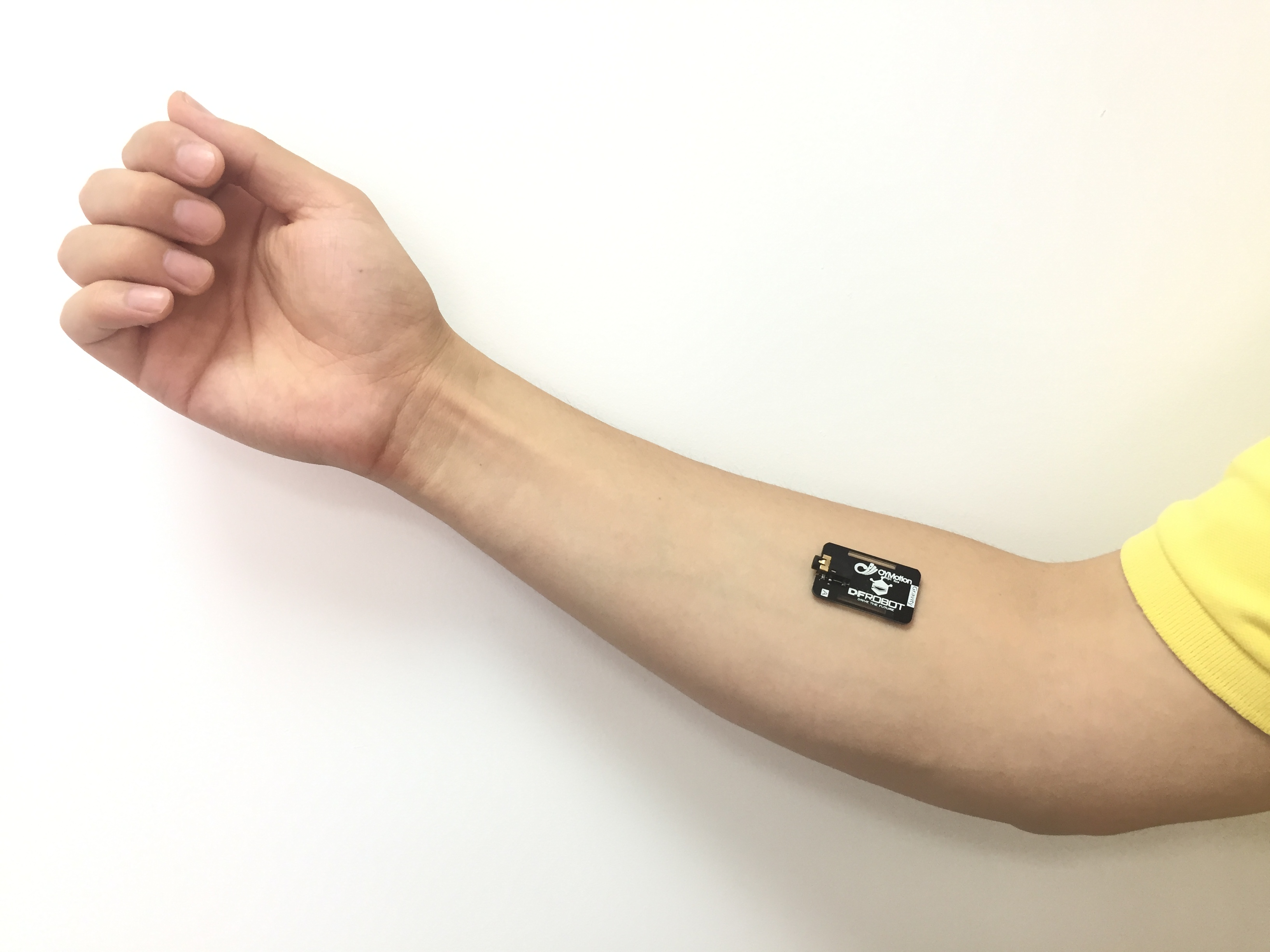
1. Check whether the power supply of your sensor is stable;
2. Please check whether the direction of the electrode patch is consistent with the direction of the muscle (as shown below), and the electrode patch should be tied to a large area of exposed skin.
3. Try pulling out the connector of the sensor electrode to see if the reading is normal.
You can also check out this quiz video:https://drive.google.com/file/d/1ANKqwHs0pEY-TzOjP-e0kYbKdSF-vMTM/view?usp=sharing
- You Reply:
The UUID is changing. You can try to execute FactoryReset or the BTS software restart in the lightbeacon application. A simple physical power failure restart may not be effective.
If there is no UUID, the iBeacon location service may not be enabled. You need to manually add location permissions for LightBeacon, otherwise the iBeacon monitoring function cannot be used. Please refer to the To turn on location services for App step in the wiki.
It is also possible that the battery included in the chassis may be low and you must replace the battery to find out.
- You Reply:
When "RX" floats or input High level, the module outputs processed value, the data is more steady, response time: 100-300ms; when input Low level, the module outputs real-time value, response time: 100ms.

- You Reply:
Please check whether the backlight of the screen is on normally, and how to adjust the potentiometer on the back of the screen with a screwdriver until the characters are clearly displayed.

- You Reply:
This phenomenon may be caused by the unstable input voltage of the power supply pin of the sensor, please replace the regulated power supply or external power supply input.
- You Reply:
As shown in the figure below, the diameter of the white circular area is 11mm.

