
- You Reply:
Hello,
The laser-cut acrylic is installed between the PCB and the bottom plate so that the bottom plate will not crush the sodering joints when tightening the screws.
I had the same confusion when I unboxed mine.
- You Reply:
Hello,
Please allow me to attach the contact information of the Lattepanda team: admin@lattepanda.com
They typically will reply to your queries within 2 business days.
Cheers.
- You Reply:
Hello,
The part number of the LED is attached below.

The documentation with complete specifications of this LED will be uploaded to the wiki page soon.
https://wiki.dfrobot.com/Gravity_AS7341_Visible_Light_Sensor_SKU_SEN0364
- You Reply:
Hello,
From my experience, the Huskylens can sometimes get pretty hot. If it functions normally and can communicate with the microcontroller that you are using, it will probably be okay.
- You Reply:
Hello,
This is what I have found,
https://www.dfrobot.com/product-2779.html
hope that this information will help
- You Reply:
Hello,
I believe that currently there is no restart command for the HUSKYLENS. To restart the device, you can add a relay which can cut off the power supply of the HUSKLENS.
- Topic: Range of WavelengthsYou Reply:
Hello,
The following diagram provides the reference data for the range of response wavelengths of the Waterproof Ambient Light Sensor. The horizontal axis represents wavelengths in units of nanometers, and the vertical axis represents the ratio.
Hope that this information will help you with your project!

- You Reply:
Hello,
Currently, the Huskylens's video feed can not be accessed, if you are using a Unihiker board (https://www.dfrobot.com/product-2691.html), Raspberry Pi, or an ESP32 S3 (https://www.dfrobot.com/product-2676.html) you can add a separate camera module to the project to stream the live feed video.
Best regards,
- You Reply:
Hello,
The SEN0463 Geiger Counter Module uses pulses to measure the radiation intensity, the voltage goes from 0 to VCC, if you are using Arduino UNO or mega it is most likely peaked at 5V. However, the measured radiation strength is in units of CPM, and the background radiation is around 25 counts per minute. This means that in most indoor or outdoor environments, the module will send at least 25 times high signals every minute (25 pulses) and when there is a radioactive source present the counts may go well beyond this value. The library for this module uses the interrupt function to capture the pulses due to this nature.
For more information please visit https://github.com/cdjq/DFRobot_Geiger
Best regards,
- You Reply:
You can try to change this address in the DFRobot_BMX160.h file to 0x69


- You Reply:
Hello,
This is unlikely that both sensors are malfunctioning, is it possible for you to provide us with a photo that shows how the sensor and boards are connected?
If you are using Arduino IDE, you can also try the following I2C scanning code :
#include <Wire.h> // Include the Wire library for I2C communication
// Setup function initializes the serial communication and I2C
void setup() {
Serial.begin(9600); // Initialize serial communication with a baud rate of 9600
Wire.begin(); // Initialize the I2C communication
Serial.println("Start I2C address scan"); // Print a message to indicate the scan is starting
}// Loop function continuously scans for I2C devices
void loop() {
byte device_address; // Variable to store the I2C device address
int nDevices; // Variable to store the number of devices found// Search for devices on the I2C bus
nDevices = Wire.scan(); // Perform the scan and store the number of devices found// Print the number of devices found
Serial.print("Number of devices found: ");
Serial.println(nDevices);// Loop through all the devices found
for (int i = 0; i < nDevices; i++) {
// Get the address of the current device
device_address = Wire.getDeviceList();// Print the device address
Serial.print("Device address: ");
Serial.print(device_address, HEX); // Print the address in hexadecimal format
Serial.println(" (0x"); // Print a prefix to indicate hexadecimal format
}// Wait for a few seconds before scanning again
delay(5000);
}
- You Reply:
Hello,
Please refer to the following wiki page: https://wiki.dfrobot.com/SKU_SEN0539-EN_Gravity_Voice_Recognition_Module_I2C_UART
The CMID for the Wake-up word “hello robot” is ID 2

Please try the following code

When you awaken the module, it should return you with the correct ID:

And this is the result that I got when I tested mine:

Hope this helps,
Cheers
- You Reply:
Hello,
Please refer to the following section in the product manual and try to calibrate the sensor:https://wiki.dfrobot.com/Analog_EMG_Sensor_by_OYMotion_SKU_SEN0240

After calibration, ensure the sensor is securely fastened to the arm.
Throughout the testing phase, the arm should remain stationary and refrain from any abrupt motions.
Best regards,
- You Reply:
Hello,
Have you tried to use an I2C scanning program to check the changed I2C address? If you are using Arduino IDE, you can try the following code.
#include <Wire.h> // Include the Wire library for I2C communication
// Setup function initializes the serial communication and I2C
void setup() {
Serial.begin(9600); // Initialize serial communication with a baud rate of 9600
Wire.begin(); // Initialize the I2C communication
Serial.println("Start I2C address scan"); // Print a message to indicate the scan is starting
}// Loop function continuously scans for I2C devices
void loop() {
byte device_address; // Variable to store the I2C device address
int nDevices; // Variable to store the number of devices found// Search for devices on the I2C bus
nDevices = Wire.scan(); // Perform the scan and store the number of devices found// Print the number of devices found
Serial.print("Number of devices found: ");
Serial.println(nDevices);// Loop through all the devices found
for (int i = 0; i < nDevices; i++) {
// Get the address of the current device
device_address = Wire.getDeviceList();// Print the device address
Serial.print("Device address: ");
Serial.print(device_address, HEX); // Print the address in hexadecimal format
Serial.println(" (0x"); // Print a prefix to indicate hexadecimal format
}// Wait for a few seconds before scanning again
delay(5000);
}
- Topic: MBT0005 - without RGB led'sYou Reply:
Hello,
The MBT0005 as I know should be an expansion board for micro: bit. The attachment file that I downloaded from this post seems like a different electrical component. Is it possible to upload another photo for the board?

Best regards,
- You Reply:
Hello,
Currently, we manually clean the forums, the spam posts usually don't last more than 24 hours.
Thank you for being so supportive of the community.
Best regards,
- You Reply:
Hello,
Please refer to the wiki link below:
https://wiki.dfrobot.com/SKU_DFR0536_Micro_bit_Gamepad_Expansion_Board
The gamepad no longer requires any extensions, you can use the controller by reading the analog and digital value of the micro: bit pins and send the commands via radio.
This is an example program: https://makecode.microbit.org/_PtgDRughPidF

- You Reply:
Hello,
The R&D department has conducted tests on this module and found that incorporating various voice lines significantly compromises its pronunciation clarity and accuracy. Therefore, they concluded that this feature would not be added to the module.
Best Regards
- You Reply:
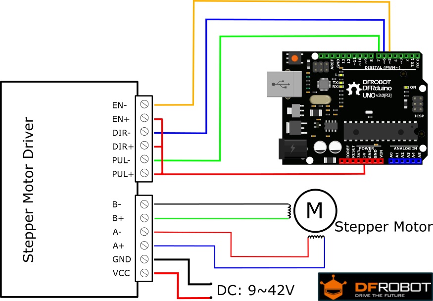
Hello,
A stepper motor does not need PWM (Pulse Width Modulation) pins for control, and it cannot be controlled with a PWM signal. However, you can use the PWM pins as regular digital pins on your Arduino board, and they will work just fine for this purpose.
- You Reply:
Hello,
Sorry, we currently don't have fritzing libraries for our boards yet.
Best regards,