- You Reply:
1. Interface: JST PH2.0 - 4pin (the pin diagram is also marked on the board: - DC ++, indicating two negative pins and two positive pins)


2. Interface: JST PH2.0 - 4pin

- Topic: Sigma WiFi AntennasYou Reply:
Did you buy FIT0657 or FIT0822?
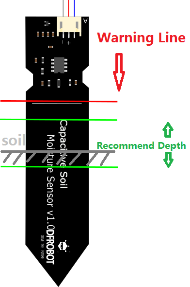
Please refer to this picture for the installation method.

- You Reply:
Please use it with ADS1115 module.
I simulate your project using ESP32-E, ADS1115, and the DAC module. (This DAC module is I2C communication, 2 channels of 0~10V or 0-5V analog voltage output with 12bit resolution and 0.5% accuracy. )
I set the DAC module to output 1.22V. At the same time, I measured the output voltage of ESP32-E as 3.29V. #define VREF 3.29
As can be seen from Figure 2, the voltage read using the ADS1115 code is 1226mv. Further using the formula in the code to convert, the final stable result is 2.17A. (This output has been rounded.)
Hope that helps.
code:
#include <Wire.h>
#include <DFRobot_ADS1115.h>
DFRobot_ADS1115 ads(&Wire);
const int ACPin = A2; //set arduino signal read pin
#define ACTectionRange 5; //set Non-invasive AC Current Sensor tection range (5A,10A,20A)
#define VREF 3.29
float readACCurrentValue()
{
if (ads.checkADS1115()){
double ACCurrtntValue = 0;
double peakVoltage = 0;
double voltageVirtualValue = 0; //Vrms
int16_t adc0;
double temp = 0;
double voltage = 0;
for (int i = 0; i < 5; i++)
{
adc0 = ads.readVoltage(0);
temp = ads.readVoltage(0);
peakVoltage += temp; //read peak voltage
delay(1);
} peakVoltage = peakVoltage / 5;
Serial.print("A0:");
Serial.print(adc0);
Serial.println("mV, ");
ACCurrtntValue = peakVoltage /1000 * 1.7675;
Serial.print(ACCurrtntValue);
/*
voltage = peakVoltage / 1000.000;//real voltage
Serial.print("real voltage:");
Serial.println(voltage);
voltageVirtualValue = voltage * 0.707; //change the peak voltage to the Virtual
//The circuit is amplified by 2 times, so it is divided by 2.
voltageVirtualValue = voltageVirtualValue / 2;
ACCurrtntValue = voltageVirtualValue * ACTectionRange;
*/
return ACCurrtntValue;
}
else
{
Serial.println("ADS1115 Disconnected!");
return 0;
}
}
void setup()
{
Serial.begin(115200);
pinMode(D9, OUTPUT);
ads.setAddr_ADS1115(ADS1115_IIC_ADDRESS0); // 0x48
ads.setGain(eGAIN_ONE); // 2/3x gain
ads.setMode(eMODE_SINGLE); // single-shot mode
ads.setRate(eRATE_128); // 128SPS (default)
ads.setOSMode(eOSMODE_SINGLE); // Set to start a single-conversion
ads.init();
}
void loop()
{
float ACCurrentValue = readACCurrentValue()/1.00; //read AC Current Value
//Serial.print("voltage: %.3fV\n", ACCurrentValue);
Serial.println(" A");
digitalWrite(D9, HIGH);
delay(500);
digitalWrite(D9, LOW);
delay(500);
}
- You Reply:
Before using the 4G or 5G module, please insert a micro-SIM card into the SIM card slot, then assemble the antennas on the module.
Then install the driver of the module after logging into the OS.
We have tested the following modules, which are working fine in the Windows 10 OS.
Quectel EM05-E
SIMCom SIM7600G-H-M2
Quectel RM500Q-GL
- Topic: YOLO IssueYou Reply:
Please refer to this sample code. It would help if you used Anaconda to create a dedicated environment for yolov8.
https://docs.ultralytics.com/models/yolov8/#performance-metrics

- You Reply:
Hi!
Please check whether there is an external 7-23V power supply, which will affect the work of the shield.
- You Reply:
Hi!
Please try to use the I2C mode and scan through the I2C address code to see if the address can be scanned.
https://www.digikey.com/en/maker/projects/raspberry-pi-pico-rp2040-i2c-example-with-micropython-and-cc/47d0c922b79342779cdbd4b37b7eb7e2
- You Reply:
Hi!
Please check if the I2C address in the code corresponds to the sensor switch. (0x45 in default)
After changing the switch, the sensor needs to be re-powered.


- You Reply:
Hi!
You might consider connecting another BME280 using SPI.
Or use an I2C Multiplexer to use some BME280 together.
https://www.dfrobot.com/product-1780.html
- You Reply:
Hi!
You can also consider making an adapter module for SIM7600G-H-M2 to convert the M.2 interface into a USB interface and connect it to the USB2.0 pin header of LattePanda.
https://www.lattepanda.com/forum/?t=876&p=1
- You Reply:
Hi!
The Lattepanda Forum may be helpful to you.
https://www.lattepanda.com/forum/?t=876&p=1
- You Reply:
Hi!
We generally use ArduinoIDE to program the Bluno. But your code doesn't seem to be ArduinoC. Could you pls tell me more details?
- You Reply:
Hi!
Sorry to hear this, I think it's likely that the Arduino Uno Wifi rev 2 underlying code is causing the HuskyLens I2C initialization failure. Have you tried UART? Maybe you can try this code. (Soft serial port green line >> D10; blue line >> D11 is being used)
test02.ino:
https://drive.google.com/file/d/1Ar08A77BB-DDxJVO0Kpz-sZcaIEDxRnP/view?usp=sharing

It may need to be developed according to the communication protocol if it still cannot be solved.
https://github.com/HuskyLens/HUSKYLENSArduino/blob/master/HUSKYLENS%20Protocol.md
- Topic: DFROBOT SEN0440 no device!You Reply:
Hi!
If none of these dangerous gases are in your office, I think it's normal for the sensor to get 0 ppm.
- You Reply:
Hi!
Please set "auto detect" and save.

Husky Lens ---------→ board
SCL---------→ SCL
SDA---------→ SDA
VCC---------→ 5V
GND---------→ GND
- You Reply:
Hi!
In arduinoIDE, what board url are you using?
- You Reply:
Hi!
Sorry, there is no tutorial for Raspberry Pi in this product wiki.

- You Reply:
Hi!
pls refer to this wiki.
SKU_DFR0975_FireBeetle_2_Board_ESP32_S3_Advanced_Tutorial-DFRobot
https://wiki.dfrobot.com/SKU_DFR0975_FireBeetle_2_Board_ESP32_S3_Advanced_Tutorial#target_9
https://www.dfrobot.com/forum/topic/320851

- You Reply:
Hi!
Sorry for the late reply.
We had fixed this issue and updated the library. pls try downloading the library and adding it to Arduino IDE.
- You Reply:
Hi!
Is there an update on data on dry soils?
Compared with my test data, the data difference between your three intervals is not that big.
The sensor data fluctuates over a long period of time.

It is recommended that you try to increase the contact area between the sensor and the soil, refer to this picture. This may have something to do with the amount of water given to the soil.